
Turbomachine fan

a technology of turbines and fans, applied in the direction of marine propulsion, vessel construction, washing machines, etc., can solve the problems of ejecting the platform, breaking the fastening, and destroying the adjoining platform, etc., and achieve the effect of simple, economic and effective solution

Active Publication Date: 2008-11-06
SN DETUDE & DE CONSTR DE MOTEURS DAVIATION S N E C M A
View PDF8 Cites 16 Cited by
  • Summary
  • Abstract
  • Description
  • Claims
  • Application Information

AI Technical Summary

Benefits of technology

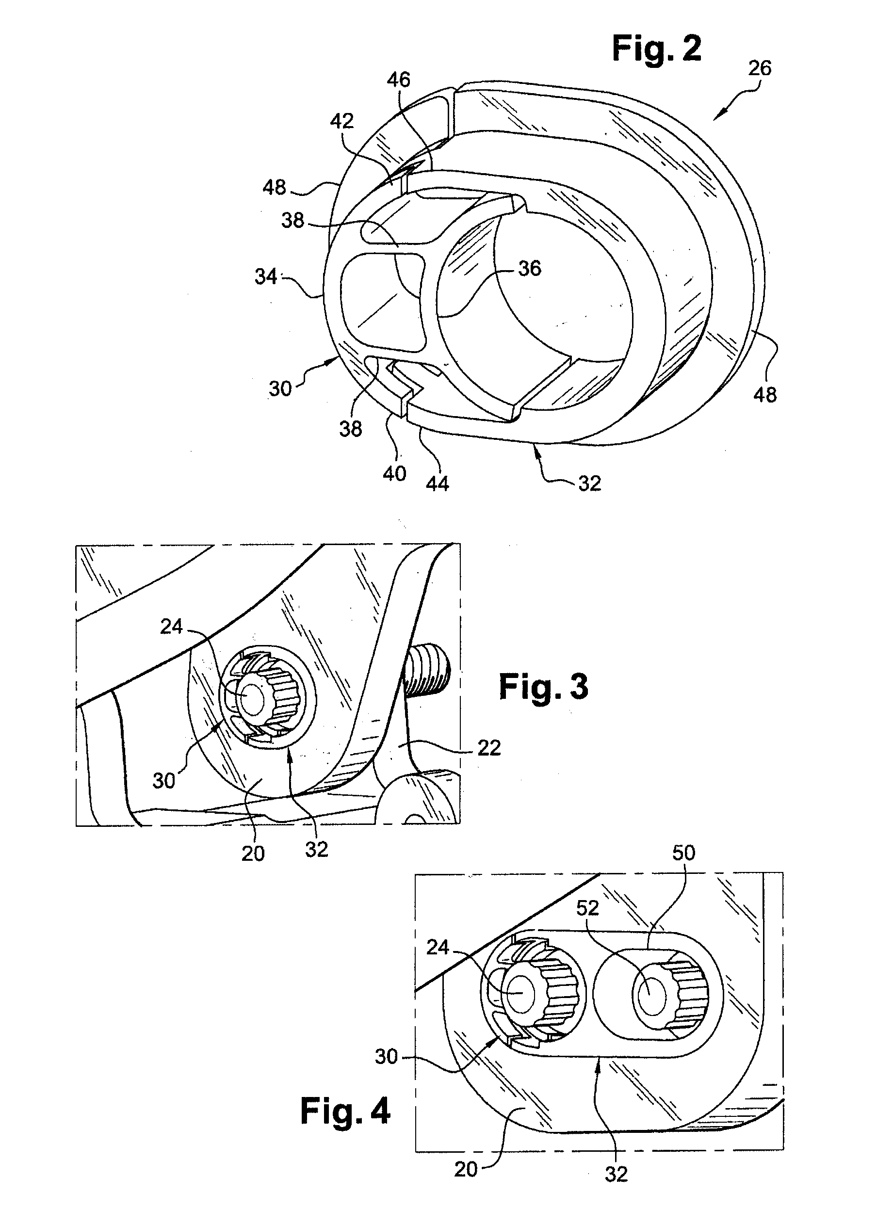
The invention provides a simple, economic, and effective solution to various problems faced by turbomachines, particularly in the event of blade loss. The invention includes a turbomachine fan with blades carried by a rotor disk and inter-blade platforms. The platforms have radial flanges with deformable parts that allow them to pivot in the event of an impact from a blade loss. The deformable parts absorb some of the energy of the impact and prevent damage to the engine. The invention also includes a two-part bush design with a rigid part and a deformable part that can be easily replaced in the event of an impact. The deformable part has two parallel half-cylinders connected by webs of material, which can absorb the energy of the impact and immobilize the platform. The invention thus facilitates maintenance operations and prevents major damage to the turbomachine.

Problems solved by technology

During the operation of the turbomachine, the breaking of the connection between a blade and the disk can result in the destruction of the adjoining platform.
Specifically, the blade then comes up against the lateral edges of the platform and / or against the flanges of the platform, thereby producing a considerable stress on the fastenings used to fasten the platform flanges to the disk flanges and possibly causing these fastenings to break and the platform to be ejected into the air flow path, and resulting in the destruction of parts of the turbomachine that are located downstream.
However, these solutions are not satisfactory since they do not impart any flexibility to the connection between the flanges of the platform and the flanges of the disk and do not allow sufficient absorption of the energy due to the impact between the blade and the platform.

Method used


Image

  • Turbomachine fan
  • Turbomachine fan
  • Turbomachine fan

Examples


Embodiment Construction

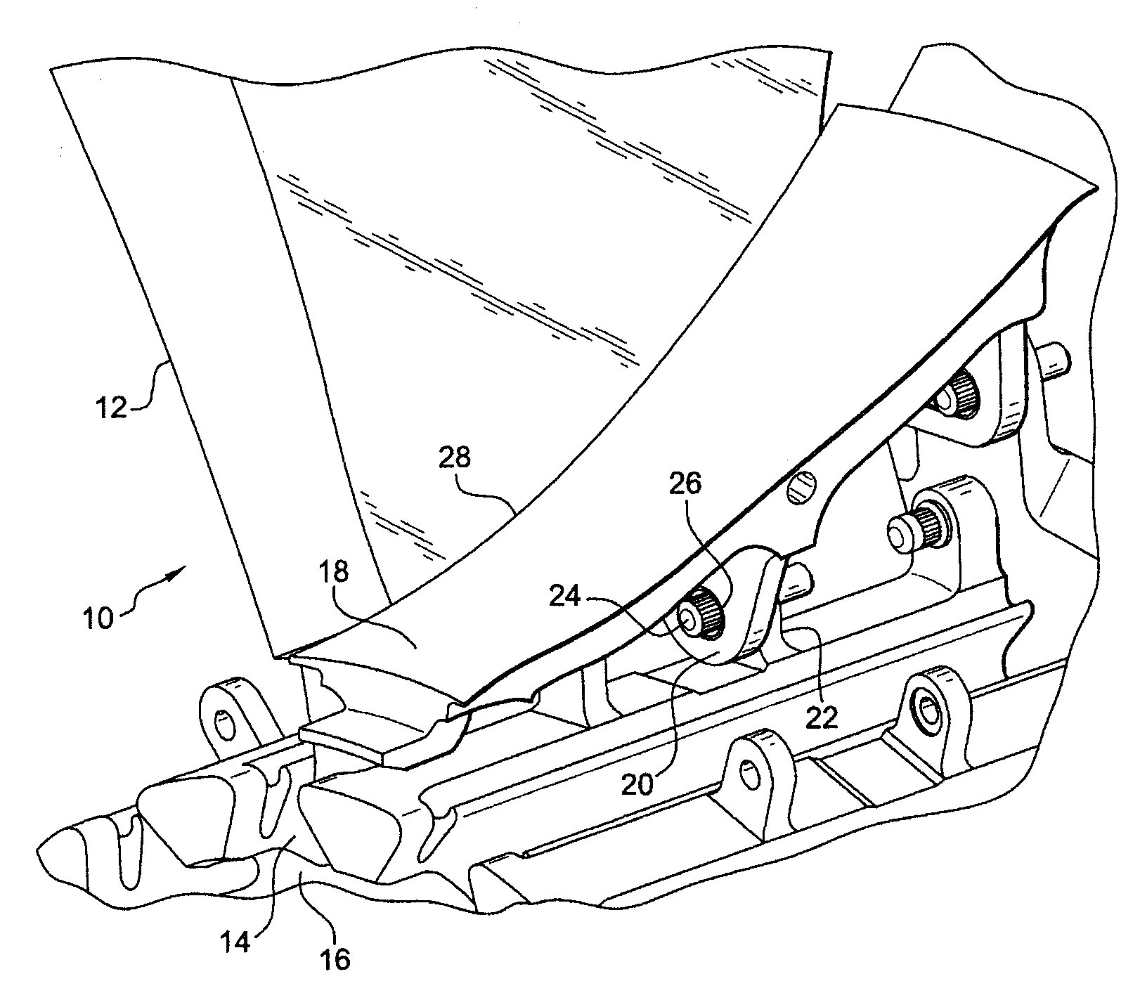
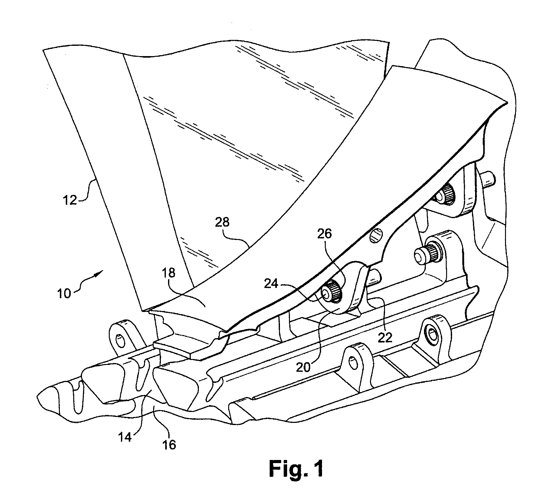
[0027]Reference will be made first of all to FIG. 1, which represents part of a fan 10 of a turbomachine. A blade 12 of the fan 10, formed by an airfoil connected at its radially internal end to a blade root, is engaged in a peripheral pocket 14 of a rotor disk 16. An inter-blade platform 18 comprises radially inwardly extending flanges 20 fastened to radially outwardly extending flanges 22 of the disk. The flanges 20 of the platform 18 are offset axially and radially. Each flange 20 of the platform is fastened by a threaded rod 24 extending along the axis of the turbomachine through a bush 26 inserted into an orifice in the flange of the platform and through a corresponding orifice in the flange 22 of the disk 12. The threaded rod receives a retaining nut at one of its ends.

[0028]In a turbomachine, the platforms 18 must be sufficiently close to the blades 12 to prevent any unwanted air flow toward the disk 16. In the event of a blade loss, the blade 12 is subject to a rotational mo...


PUM


Abstract

A turbomachine fan (10) comprising blades (12) and inter-blade platforms (18) having radial flanges (20) fastened to flanges (22) of a rotor disk (16) by means of threaded rods inserted into bushes (26) mounted in orifices in the flanges of the platforms (18), wherein each bush (26) comprises at least one deformable part (30) interposed transversely between the threaded rod (24) and an edge of the orifice in which the bush (26) is mounted, this deformable part (30) being intended to allow the platform (18) to pivot in the event of an impact of a blade (12) against the platform (18) and to absorb some of the energy of the impact.

Description

BACKGROUND OF THE INVENTION AND DESCRIPTION OF THE PRIOR ART[0001]In a known manner, the fan provided at the upstream end of a turbojet comprises blades carried by a rotor disk, with platforms arranged between the blades and fastened by radial flanges to flanges of the disk by means of threaded rods inserted through bushes mounted in orifices in the flanges of the platform and through flanges of the disk, these platforms making it possible to guide the air stream entering the turbomachine and to avoid unwanted air flows toward the disk.[0002]During the operation of the turbomachine, the breaking of the connection between a blade and the disk can result in the destruction of the adjoining platform. Specifically, the blade then comes up against the lateral edges of the platform and / or against the flanges of the platform, thereby producing a considerable stress on the fastenings used to fasten the platform flanges to the disk flanges and possibly causing these fastenings to break and t...

Claims


Application Information

Patent Timeline
Patent Type & Authority Applications(United States)
IPC IPC(8): F01D5/30
CPCF01D5/22F01D5/3023F01D5/3053F16B2043/008F01D21/045F05B2260/301F16B43/00F01D11/008
Inventor BELMONTE, OLIVIERGOGA, JEAN-LUC CHRISTIAN YVON
Owner SN DETUDE & DE CONSTR DE MOTEURS DAVIATION S N E C M A
Learn More