Print Head Shuttle with Active Cooling

a technology of active cooling and print head, which is applied in the direction of printing, power drive mechanisms, inking apparatuses, etc., can solve the problems of wasting time, wasting time, and wasting resources, and achieve the effect of accurate positioning of print heads

Inactive Publication Date: 2008-11-06
AGFA NV
View PDF7 Cites 21 Cited by
  • Summary
  • Abstract
  • Description
  • Claims
  • Application Information

AI Technical Summary

Benefits of technology

[0008]In order to overcome the problems described above, preferred embodiments of the present invention provide a print head shuttle having the specific features and a method of preserving the stability of a print head shuttle as set forth below. With the print head shuttle according to preferred embodiments of the present invention, the thermal and dimensional stability of the mechanical references used for accurately positioning of the print heads is preserved.

Problems solved by technology

Several problems arise when using larger print head shuttles in digital printer configurations.
As print head shuttles get larger, they get heavier which complicates fast and accurate movement of the shuttle.
As print head shuttles get larger, the left and right abutments of the shuttle on the printer frame diverge and the shuttle structure becomes more susceptible to bending and torsion.
As print head shuttles get larger, the print width of a single print stroke increases and the throw-distance, defined as the distance between the print head's printing elements (e.g., the ink jet nozzles) and the print surface of the printing medium, across the entire print stroke, become more difficult to control within acceptable tolerances.
Additionally, as print head shuttles get larger, they carry more print heads and the accurate positioning of the print heads over the full width of the shuttle becomes more difficult.
A general problem associated with large mechanical structures like print head shuttles for industrial printing systems is their thermal and dimensional stability during operation.
These are just some of the problems that arise when scaling up existing print head shuttle concepts for industrial type printing equipment.

Method used


Image

  • Print Head Shuttle with Active Cooling
  • Print Head Shuttle with Active Cooling
  • Print Head Shuttle with Active Cooling

Examples


Embodiment Construction

[0018]While the present invention will hereinafter be described in connection with preferred embodiments thereof, it will be understood that it is not intended to limit the invention to those preferred embodiments.

One Preferred Embodiment of a Digital Printer Embodying the Present Invention

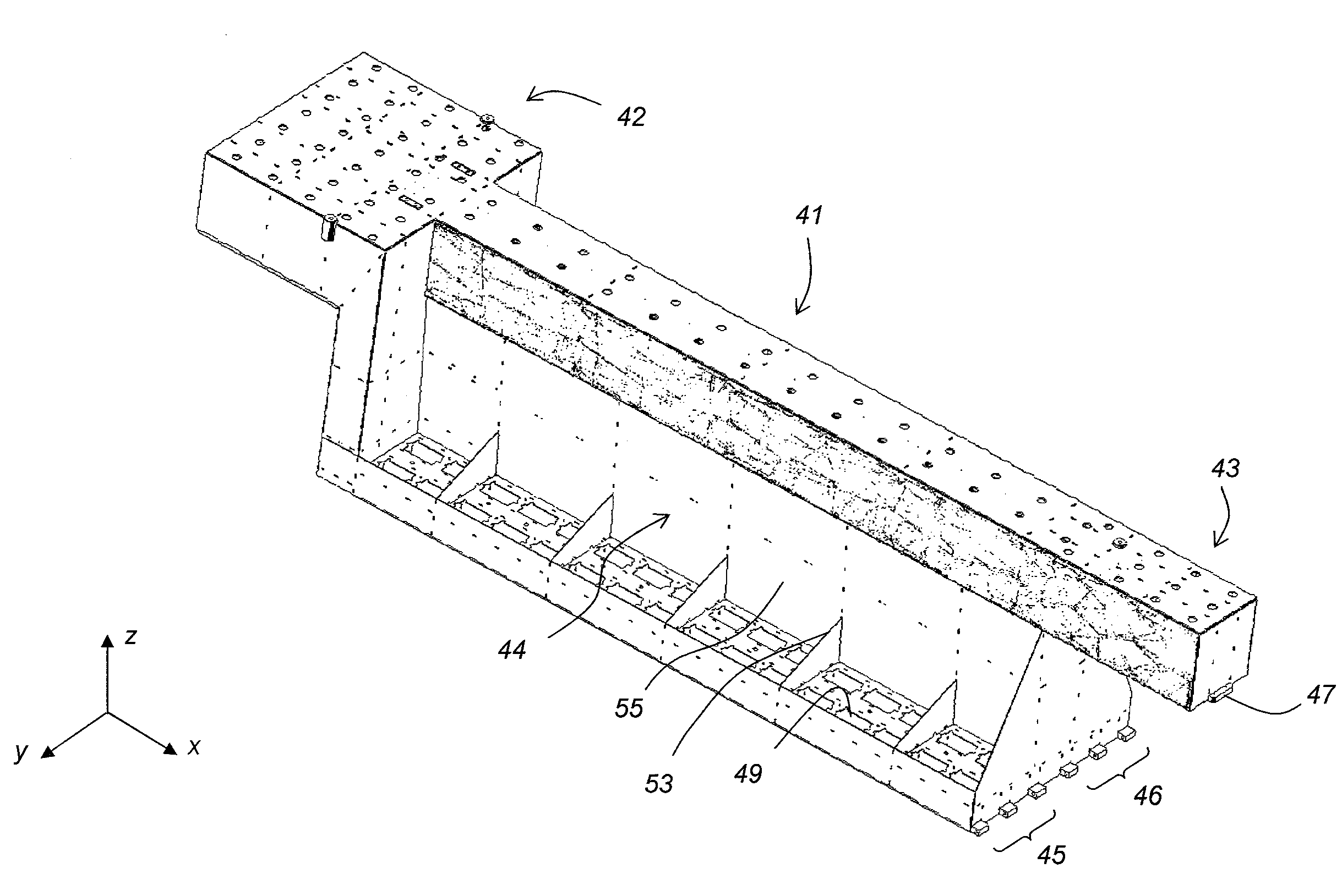
[0019]A digital printer according to a preferred embodiment of the present invention is shown in FIG. 1. The digital printer 1 includes a printing table 2 arranged to support a printing medium 3 during digital printing. The printing table is substantially flat and can support flexible sheets of media with a thickness as low as tens of micrometers (e.g., paper, transparency foils, adhesive PVC sheets, etc.), as well as rigid substrates with a thickness up to some centimeters (e.g., hard board, PVC, cartons, etc.). A print head shuttle 4, including one or more print heads, is designed for reciprocating back and forth across the printing table in a fast scan direction FS and for repositioning across ...


PUM


Abstract

A print head carriage for holding a print head in a printing system includes a print head carriage framework having a plurality of print head positioning references for defining a position of the print head onto the print head carriage framework, and a cooling channel in thermal contact with the print head carriage framework for controlling the temperature of the print head carriage framework such that the positional stability of the plurality of print head positioning references on the print head carriage framework is preserved.

Description

CROSS-REFERENCE TO RELATED APPLICATIONS[0001]This application is a 371 of PCT / EP2006 / 062698, filed May 30, 2006. This application claims the benefit of U.S. Provisional Application No. 60 / 692,199, filed Jun. 20, 2005, which is incorporated by reference. In addition, this application claims the benefit of European Application No. 05104627.4, filed May 30, 2005, which is also incorporated by reference.BACKGROUND OF THE INVENTION[0002]1. Field of the Invention[0003]The present invention relates to a solution for preserving the dimensional stability of a print head carriage framework. More specifically, the present invention is related to a device and method for controlling the temperature of a print head carriage framework.[0004]2. Description of the Related Art[0005]In industrial printing applications, print throughput is an important characteristic of a printing device. One of the parameters determining print throughput in digital printers using a reciprocating print head configurati...

Claims


Application Information

Patent Timeline
Patent Type & Authority Applications(United States)
IPC IPC(8): B41J11/22
CPCB41J25/34B41J29/377B41J2202/08
Inventor VERLINDEN, BARTVERHOEST, BARTVAN DE WYNCKEL, WERNERBRALS, ALBERT
Owner AGFA NV
Why Eureka
Try Eureka