
Method and apparatus for channel coding and decoding

a channel and channel technology, applied in the field of channel coding and decoding, can solve the problem that nothing is disclosed whether or how the findings can be generalized

Inactive Publication Date: 2008-11-06
THOMSON LICENSING SA
View PDF7 Cites 2 Cited by
  • Summary
  • Abstract
  • Description
  • Claims
  • Application Information

AI Technical Summary

Benefits of technology

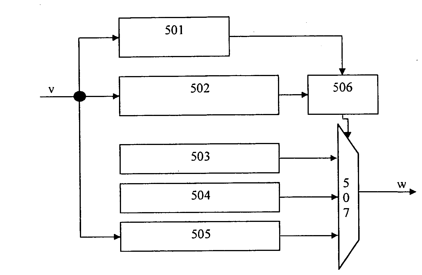
[0009]The invention has recognized that with a code replacement scheme as disclosed in U.S. Pat. No. 6,369,724, it may be seen as a drawback that a predetermined single predetermined code sequence is always used. A replacement scheme allowing to select and apply one replacement pattern out of a set of several such patterns, would offer the advantage that characteristics of the resulting bitstream, like e.g. its running digital sum, can be influenced by the selection.
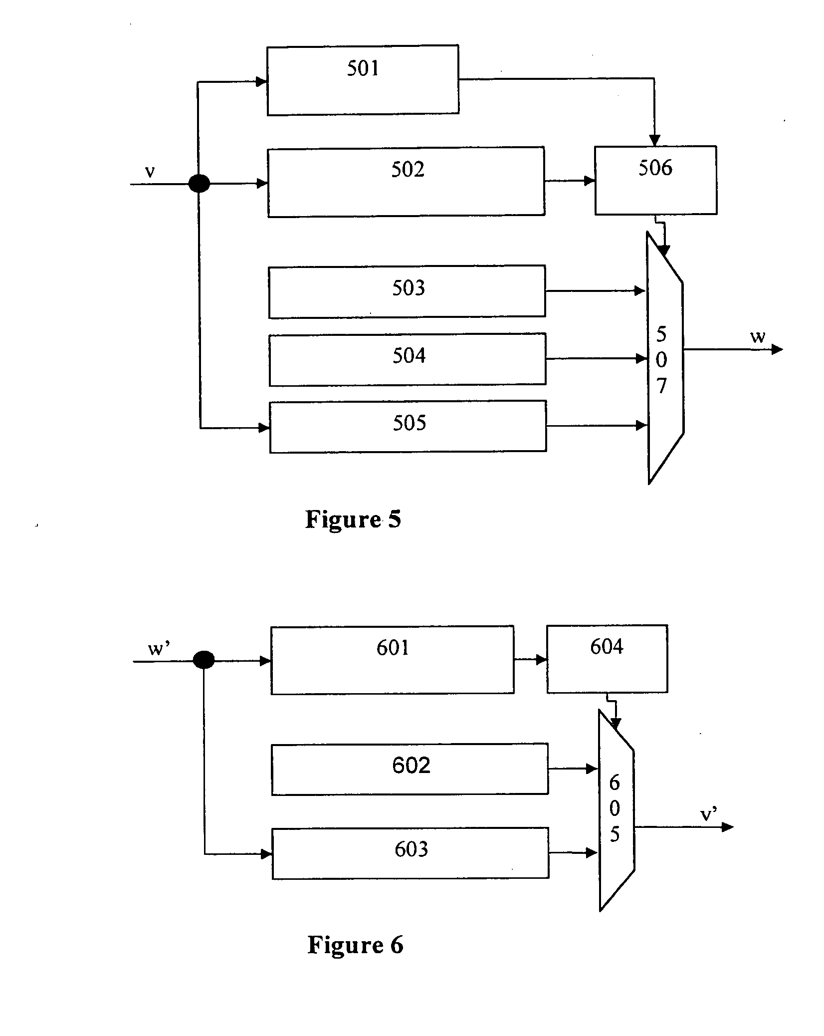
[0011]With other words, the invention proposes a channel encoding method and apparatus, where a traditional (d,k1)-encoder or -encoding is combined with a separate postprocessing stage which achieves compliance with a RMTR constraint. The postprocessing does so by substituting those bit sequences also termed forbidden patterns, which would violate the RMTR constraint, by other bit sequences termed replacement patterns which are outside the internal maximum runlength limit k1 but within the limit k>k1. The invention enables that the postencoding step provides alternative replacement patterns to be used for replacing RMTR violating bit patterns. By appropriately choosing between the alternative replacement patterns, characteristics and properties of the resulting bitstreams, like the low frequency content of the output bitstream as described by the running digital sum RDS, can advantageously be influenced.
[0016]Using these patterns has the advantage that the replacement patterns provide opposite polarity contributions to the Running Digital Sum of the NRZI modulated signal.
[0019]Advantageously, in this method, the trigger pattern consists of [1][0](k)[1][0](t), and the decoded pattern consists of [1] [[0](d)[1]](r+1). This has the advantage, that a single trigger pattern allows to perform the inverse replacement, no matter which one of the replacement patterns has been used in the encoder side.

Problems solved by technology

The method and means described in WO 00 / 03392 can be seen to have the disadvantage that they employ an extended finite state machine (FSM) which is an indication of a more complex realization.
Also, nothing is disclosed whether or how the findings can be generalized.

Method used


Image

  • Method and apparatus for channel coding and decoding
  • Method and apparatus for channel coding and decoding
  • Method and apparatus for channel coding and decoding

Examples


Embodiment Construction

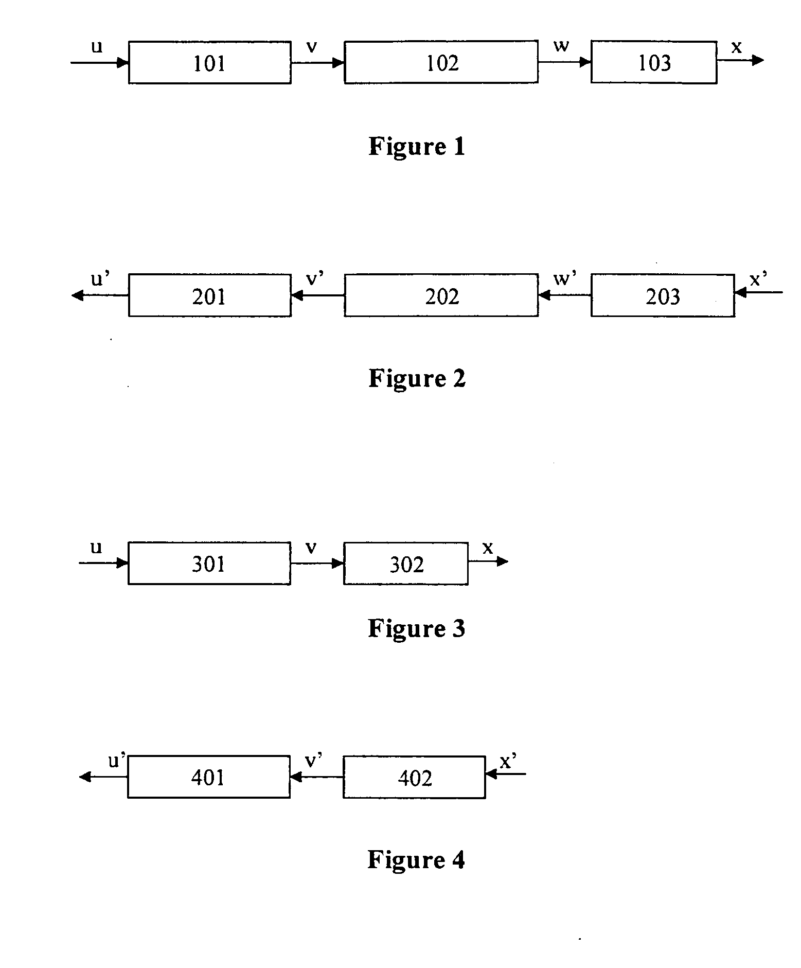
[0031]In the prior art RLL-encoder shown in FIG. 3, the dk-encoder 301 does not take care of any RMTR limitation, so that any repetitive pattern of the form

[0](d+1)[1] [[0](d)[1]](ρ) [0](d+1)

having a number ρ, 1≦ρ≦∞ of repeated minimum runlengths might appear in the sequence of constrained tuples v. Among these patterns, the ones having ρ>r are RMTR violating patterns which must be eliminated. In this, the notation “[x](y)” as defined above is used recursively and is generalized by defining that the special case of [x](0) shall be interpreted as the empty string or bitstream, regardless of the value of x.

[0032]FIG. 1 shows a block diagram of an RMTR-obeying RLL-encoder according to the invention. The encoder has a conventional dk-encoder 101 obeying a runlength limitation of (d,k1), and a conventional precoder 103 for the NRZI modulation and mapping. According to the invention, an RMTR-encoder 102 is placed between the dk-encoder 101 and the precoder 103.

From a sequence of data tup...


PUM


Abstract

In a channel encoder comprising a dk-encoder stage and a precoding stage, obeyance of a repeated minimum transition runlength constraint is achieved because, between the dk-encoder and the precoder, data are passed through an RMTR encoder which replaces occurrences of a forbidden pattern by a current replacement pattern having the same length as the forbidden pattern. By appropriately selecting current replacement patterns from a predefined set of two different replacement patterns, DC-control can be achieved for the encoder output. The corresponding decoder is described, which also employs pattern replacement.

Description

FIELD OF THE INVENTION[0001]The present invention relates to channel coding and decoding sometimes also termed modulation and demodulation, in particular to Repeated Minimum Transition Runlength limited coding.BACKGROUND[0002]Storage as a transformation of signals in time can be modelled as a bandlimited channel, and for digital signal readout in particular, the bit clock is commonly regenerated from the read out signal. Both facts are reasons that Run-Length Limited or RLL channel codes are used on digital storage media. Known as (d,k) codes, they convert any sequence of arbitrary payload words into a sequence of channel words that has at least d and at most k “0”s between consecutive “1”s. In a subsequent transcoding or precoding stage, the sequence containing the thus isolated “1”s is converted to an output signal where each of the “1”s in the sequence causes a state change in the output signal. In digital optical storage, such state changes are from “pit” to “space” or vice vers...

Claims


Application Information

Patent Timeline
Patent Type & Authority Applications(United States)
IPC IPC(8): H03M7/00
CPCH03M5/145H03M7/00H03M7/40H03M13/00
Inventor THEIS, OLIVERTIMMERMANN, FRIEDRICH
Owner THOMSON LICENSING SA
Learn More