
Stowable antenna for tpms sensor

a technology of tire pressure monitoring system and antenna, which is applied in the direction of antenna, tyre parts, tyre measurement, etc., can solve the problems of reducing the range of the sensor, preventing wireless communication altogether, and not producing acceptable arrangemen

Inactive Publication Date: 2008-11-06
TRANSENSE TECH
View PDF6 Cites 1 Cited by
  • Summary
  • Abstract
  • Description
  • Claims
  • Application Information

AI Technical Summary

Benefits of technology

[0006]A sensor assembly in accordance with the present invention has the advantage that the antenna can be stored in its folded position during installation of the sensor on a wheel and more particularly when a tire is being fitted, in which position the antenna is significantly less likely to be damaged, and can then be released for use after the tire has been fitted and the risk of damage passed.
[0011]In an alternative arrangement, the restraining means may be configured to release the antenna when air is supplied to the tire. This may be achieved by the restraining means interacting with the air as it comes through the inflation valve, the pressure of the incoming air moving or otherwise releasing the restraining means so as to release the antenna. For example, the restraining means such as a strap may extend across the inflation valve so as to block it, the inflation air blowing the restraining means out of the way, causing release of the antenna. In another arrangement, the restraining means may be responsive to the pressure surrounding the housing, releasing the antenna when the pressure reaches a predefined level. For example, a small balloon or the like may be positioned to block an opening through which the antenna must pass in order to be released and thereby the antenna is held in its folded position, the size of the balloon decreasing as the pressure in the tire increases until it is small enough to pass through the opening, thereby freeing the antenna. The pressure dependent release systems have the advantage that the tire will need to be partially inflated before the antenna is released, thereby further avoiding the possibility of damage due to the weight of the wheel and possibly the vehicle sitting on the antenna once it has been released if the orientation of the wheel happens to be with the antenna pointing downwards.

Problems solved by technology

In some designs, the antenna is enclosed within the sensor housing, but for some applications, this arrangement has been found not be produce acceptable results and instead an external aerial is provided on the sensor which typically extends away from the sensor into the space formed between the wheel and tire when inflated.
However, this presents problems when a tire is being fitted to a wheel.
As the bead of the tire is moved across the outer surface of the wheel during fitting, it can engage the antenna unless care is taken by the fitter, resulting in damage to the aerial and hence reducing the range of the sensor or even preventing wireless communication altogether.

Method used


Image

  • Stowable antenna for tpms sensor
  • Stowable antenna for tpms sensor
  • Stowable antenna for tpms sensor

Examples


Embodiment Construction

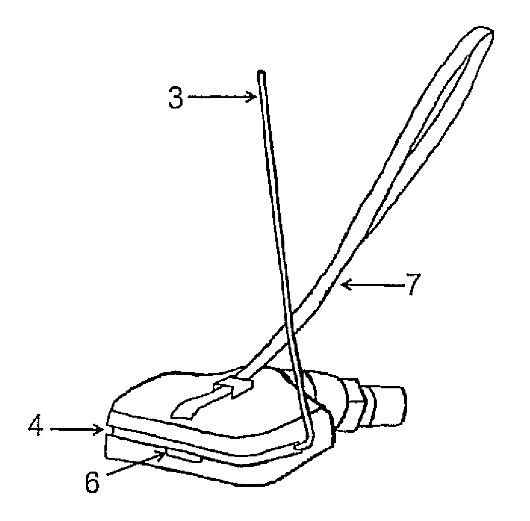
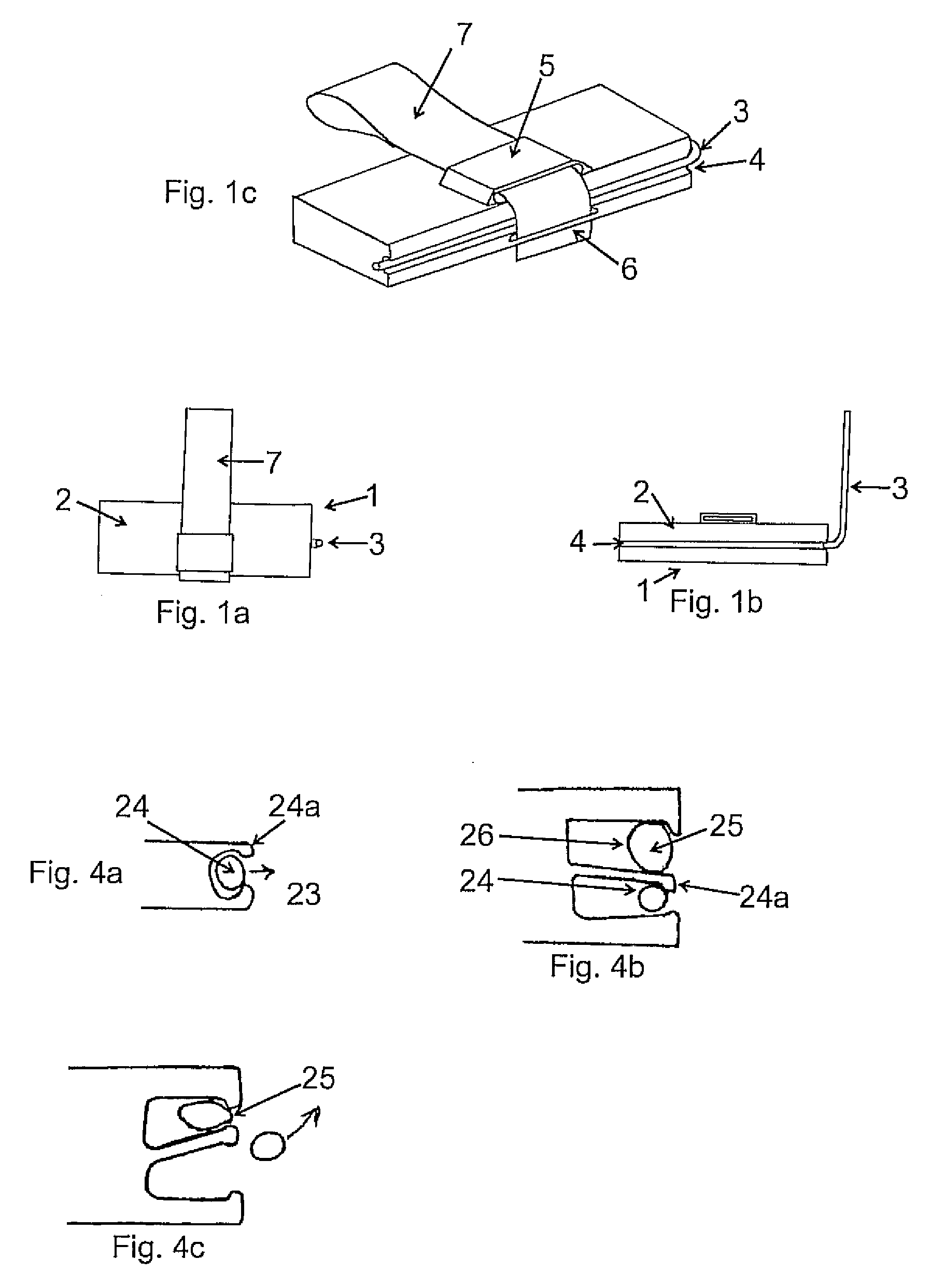
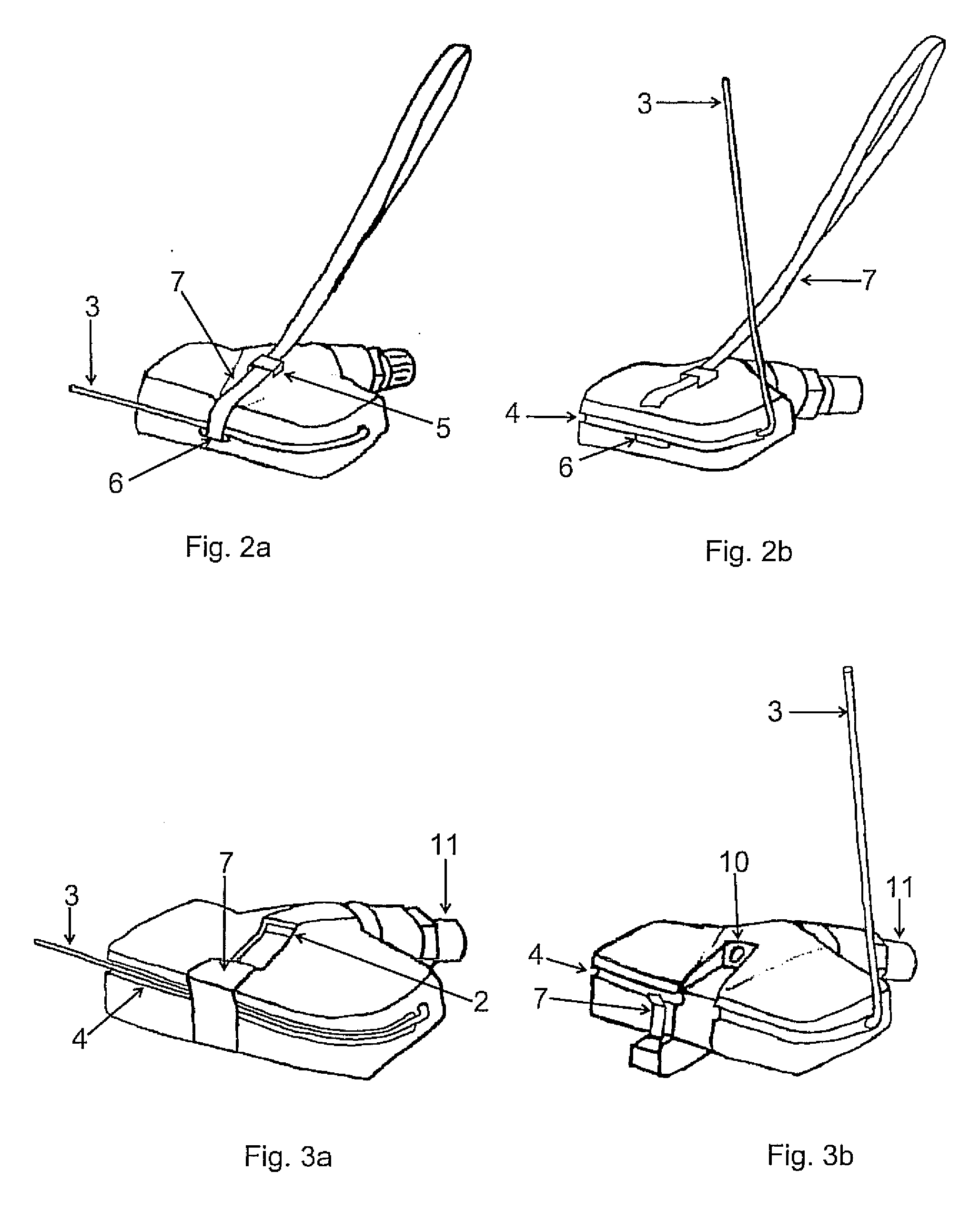
[0026]Referring first to FIGS. 1a to 2c, there is shown a sensor assembly, generally indicated at 1, comprising a housing 2 in which is mounted a tire pressure monitoring sensor (not shown). The sensor itself may be of any conventional type and will not be described in any detail here. Extending from the housing 2 is an antenna 3, which is connected to the sensor inside the housing 2 for enabling wireless RF communication between the sensor and a remote monitoring assembly (not shown) in a well known manner.

[0027]The antenna is made of a resiliently flexible material such as Ormiston 1×7 0.6 mm with heat shrink and when unrestrained, upstands from the housing 2 as shown in FIG. 2b so as, in use, to extend into the pressurised chamber formed between a wheel and a tire with which the sensor is being used. A channel or groove 4 extends laterally around the side of the housing from the point at which the antenna 3 passes through, the antenna 3 being foldable so as to lie in the channel ...


PUM


Abstract

A tire pressure monitoring system (TPMS) sensor assembly 1 has a housing 2, a pressure sensor mounted in the housing 2 and an antenna 3 connected to the sensor and extending exteriorly of the housing 2 for effecting wireless communication between the sensor and a remote module. The antenna 3 is moveable between a folded position in which it extends around at least a part of the housing 2 so as to lie substantially in the plane of the housing 2 and an erect position in which it upstands from the housing 2 so as, in use, to extend into the inflation area formed between a wheel and tire. The antenna 3 is biased towards its erect position, and further includes a releasable restraining strap 7 for restraining the antenna 3 in its folded position.

Description

BACKGROUND OF THE INVENTION[0001]1. Field of the Invention[0002]The present invention relates to wireless tire pressure monitoring system (TPMS) sensors and more particularly to such sensors which have an external aerial for achieving wireless communication with a receiver unit.[0003]2. The Prior Art[0004]Wireless sensors are well known for use in tire pressure monitoring systems, the sensor being located within the inflation area of a wheel / tire assembly so as to be exposed to the pressurised fluid contained therein and then communicating wirelessly, such as by R / F communication, with a receiver located remotely from the wheel, such as in the wheel arch. In order, then, to achieve the necessary communication, the sensor must include some sort of antenna for broadcasting and receiving signals. In some designs, the antenna is enclosed within the sensor housing, but for some applications, this arrangement has been found not be produce acceptable results and instead an external aerial ...

Claims


Application Information

Patent Timeline
Patent Type & Authority Applications(United States)
IPC IPC(8): B60C23/00
CPCB60C23/0452B60C23/0493G01L17/00B60C23/0433H01Q1/2241H01Q1/325
Inventor DIXON, BRYN JAMESNOWELL, ALDRIAN SIMON
Owner TRANSENSE TECH
Learn More