
Load Monitor

Inactive Publication Date: 2008-11-06
EMOTRON
View PDF13 Cites 47 Cited by
  • Summary
  • Abstract
  • Description
  • Claims
  • Application Information

AI Technical Summary

Benefits of technology

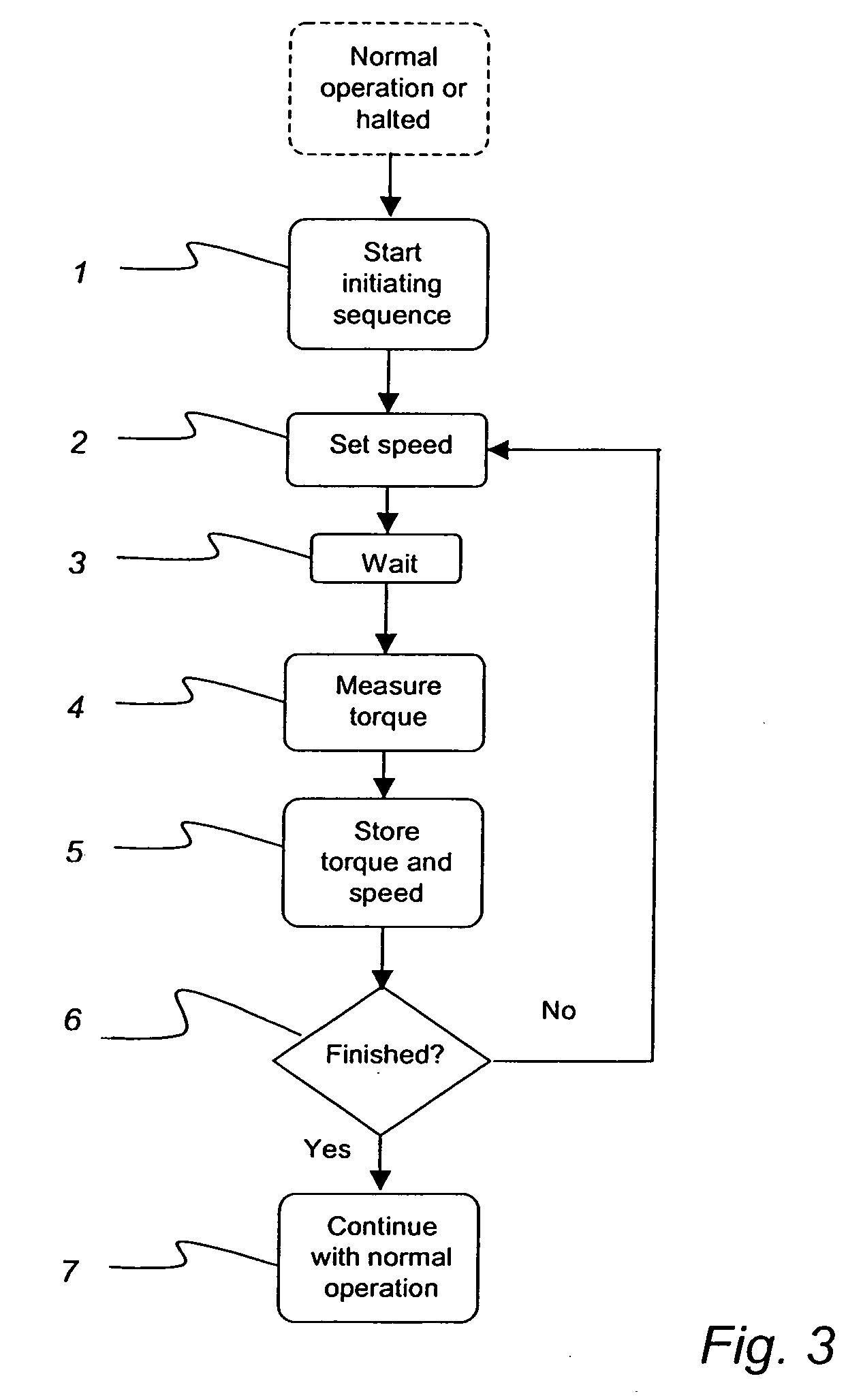
[0012]According to one embodiment of the present invention, the method further comprises the act of automatically collecting said plurality of stored torques and speeds during an initiating sequence. Thereby, the collection of the plurality of torques and speeds becomes swift, easy and flexible, as compared to for example collection of the torque and speed parameters by manually stepping up the motor speed, measuring the torque and registering the speed.
[0017]In an another embodiment, which is an alternative to the one of computing the load limit value in connection with each measurement of the torque during normal operation, the method further comprises the acts of computing a plurality of load limit values as functions of said plurality of stored torques and speeds and the predetermined deviation value during an initiating sequence before said normal operation, and storing the computed load limit values during said initiating sequence. Instead of saving memory space, computing power may be saved in this embodiment, which may be advantageous for some applications.

Problems solved by technology

Even though the above mentioned methods of load monitoring works perfectly well in applications such as the one exemplified above, there are other applications in which the above methods of load monitoring are not satisfying, e.g. in varying speed applications.
The problem is that operational disturbances are not always detected by the load monitor even though maximum and minimum load limits are set based on the actual load.
As an example, in a pump application an operational disturbance may be caused by a damaged pipe, e.g. a hole in a pipe or a broken pipe, resulting in decreasing pressure in the pipes and thus the load on the motor is decreased.
Another cause of operational disturbance may be the presence of none desired objects in the pipe, these may result in increased pressure and thus the load on the motor is increased.

Method used


Image

  • Load Monitor
  • Load Monitor
  • Load Monitor

Examples


Embodiment Construction

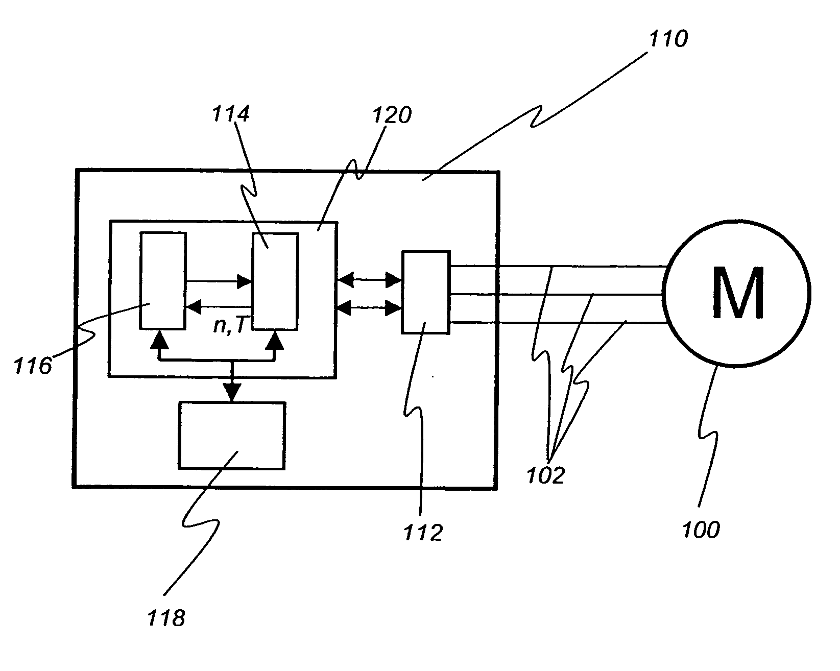
[0033]In FIG. 1 an electric motor 100 receiving its power supply 102 from a frequency converter 110 is shown. The frequency converter 110 is arranged to vary the speed of the electrical motor 100 by controlling the voltage and / or the current by means of power electronics 112 in the frequency converter 110. The control of the power electronics is performed by means of a controller 114.

[0034]According to one embodiment of the invention a load monitor 116 is arranged in the frequency converter 110. The information needed by the load monitor may then be provided directly by the frequency converter 110 or the controller 114 of the frequency converter 110. The information may be represented by data transferred over a data bus or at least a signal carrying the information over a signal line. The information provided to the load monitor may be information representing the present torque T of the motor and information representing the present speed n of the motor.

[0035]According to one embod...


PUM


Abstract

A load monitor for monitoring the load of a motor comprises a Central Processing Unit (CPU) and a memory. During normal operation of the motor, the load monitor is arranged to repeatedly measure the torque and registering the speed of the motor. In connection with each measurement of the torque and registering of the speed, the load monitor determines a load limit value valid for the registered speed, which load limit value is a function of a plurality of torques and speeds and a predetermined deviation value stored in the memory. The measured torque is then compared with the determined load limit value and if the measured torque is not within an acceptable range limited by the determined load limit value then an appropriate action is taken.

Description

TECHNICAL FIELD OF THE INVENTION[0001]The present invention relates generally to a load monitor or load indicator for a motor. More specifically, the invention also relates to methods for initiating monitoring and for monitoring the load of a motor and to a frequency converter for driving a motor and including a load monitor.BACKGROUND OF THE INVENTION[0002]Load monitors are often used for protecting electrical motor systems from underload and overload. Load monitors in fixed frequency applications, such as mains connected or soft starter driven motors, are fully described by a normal load parameter and margins to define under- / overload conditions from this normal load. Basically this is how stand alone load monitors or load monitors included in motor drive systems works.[0003]In WO 99 / 25049 A1, a load monitor for an electric motor is disclosed. This load monitor calculates, by a command from a user when the motor is running normally, the limits for under- / overload from the actual l...

Claims


Application Information

Patent Timeline
IPC IPC(8): H02P6/08
CPCH02P23/0036H02P23/0004
Inventor BOJRUP, MARTINJONSSON, TOMSPARRENBOM, NIKLAS
Owner EMOTRON
Learn More