Conical Crusher

a technology of conical crusher and axial bearing, which is applied in the field of conical crusher, can solve the problems of accelerating wear of said components, and relative low rotation speed of the conical crusher, and achieves the effect of increasing the lifespan of axial bearing components, reducing and even practically nonexistent oscillation amplitudes

Active Publication Date: 2008-11-06
METSO OUTOTEC (FINLAND) OY
View PDF3 Cites 10 Cited by
  • Summary
  • Abstract
  • Description
  • Claims
  • Application Information

AI Technical Summary

Benefits of technology

[0013]Due to the drawbacks mentioned above and related to the prior art solution, it is an objective of the present invention to provide a conical crusher of the type illustrated in FIG. 1 and described above and which has the axial bearing that supports the cone head subjected to very reduced and even practically nonexistent oscillation amplitudes, facilitating the lubrication and increasing the lifespan of the axial bearing components of the cone head.
[0014]It is a further objective of the present invention to provide a conical crusher as mentioned above, which presents a lubrication that provides the formation of a hydrostatic support in the axial bearing of the cone head, in order to prevent the metal-metal contact, thereby increasing the lifespan of the bearing components and allowing the latter to present smaller dimensions.
[0015]It is also a further objective of the present invention to provide a conical crusher as mentioned above, whose cone head is prevented from rotating around its axial axis, in the same direction of rotation of the tubular eccentric.

Problems solved by technology

Although said axial bearing of the cone head 70 is made with provision of oil in the spherical bearing 50, the relatively low rotation speed of the conical crushers does not allow the formation of a hydrodynamic wedge in the axial bearing.
These known solutions thus present the inconvenient of subjecting the axial bearing 50 to excessive loads, which tend to cause an accelerated wear of said component, due to the difficulty in obtaining an adequate lubrication by the simple supply of oil to the bearing.
Another inconvenient of the known solutions refers to the fact that the cone head is not prevented from rotating in the same direction of the tubular eccentric, when the conical crusher operates with zero load.

Method used


Image

  • Conical Crusher
  • Conical Crusher
  • Conical Crusher

Examples


Embodiment Construction

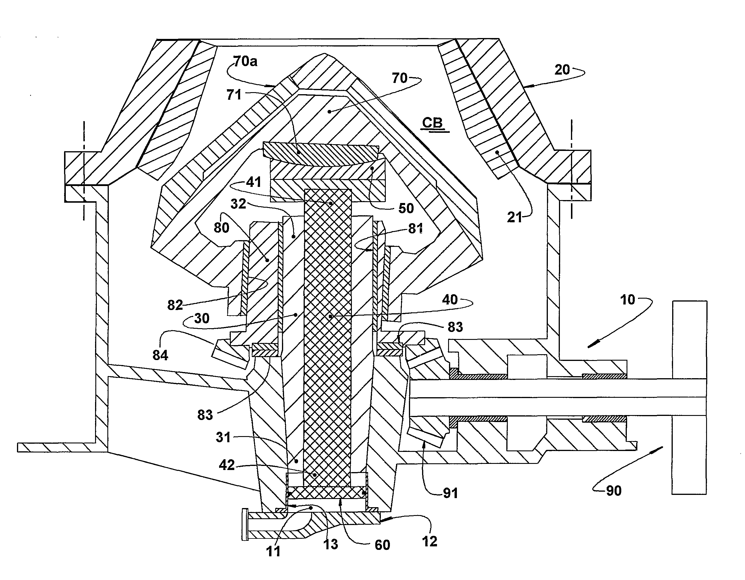
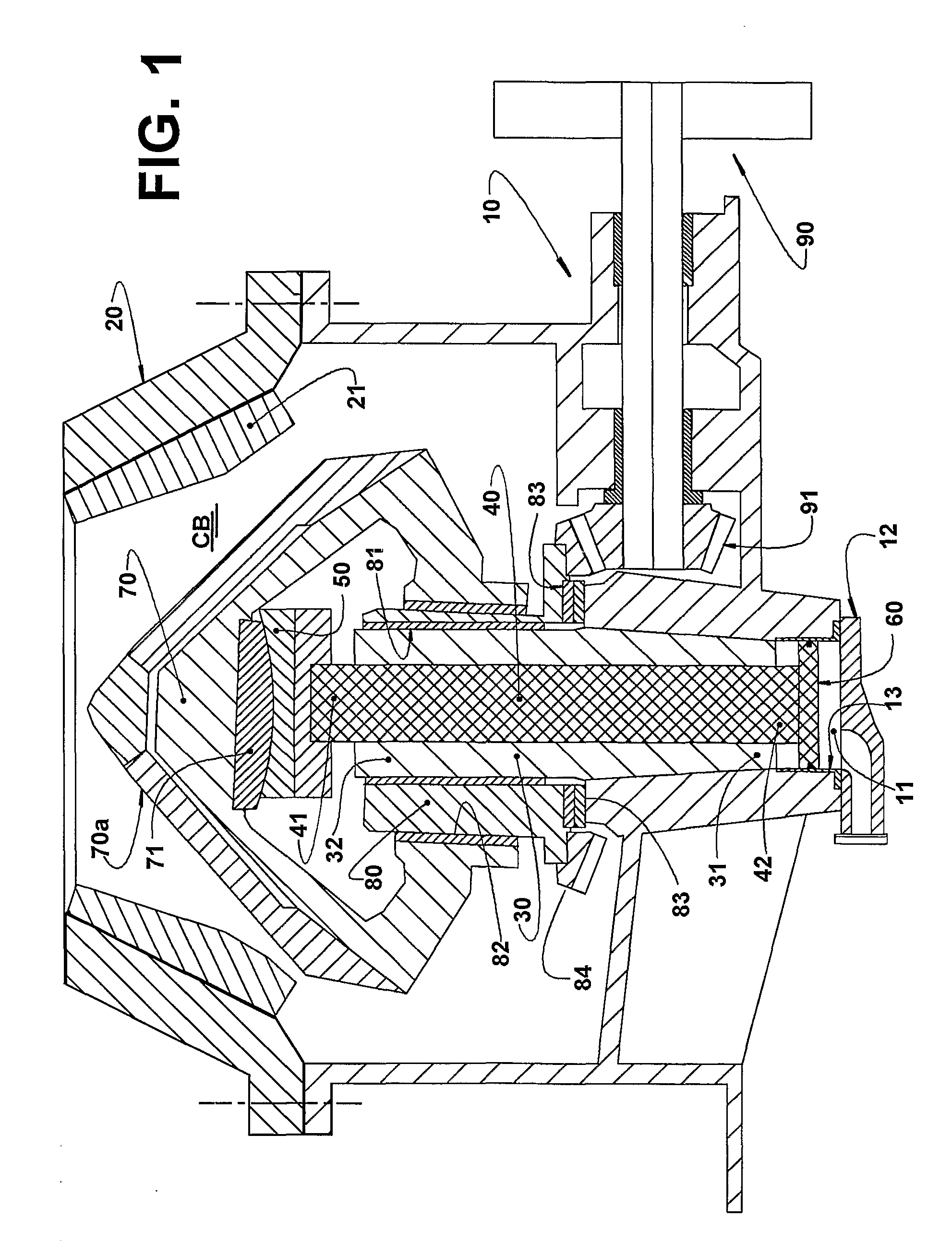
[0024]As already mentioned, the invention is applied to a conical crusher of the type illustrated in FIG. 1 and comprising a structure 10 in which is superiorly adapted an upper housing 20 built by any manner well known in the art, said upper housing 20 being internally provided with a lining 21 of a material adequate to withstand the crushing loads to which it is subjected.

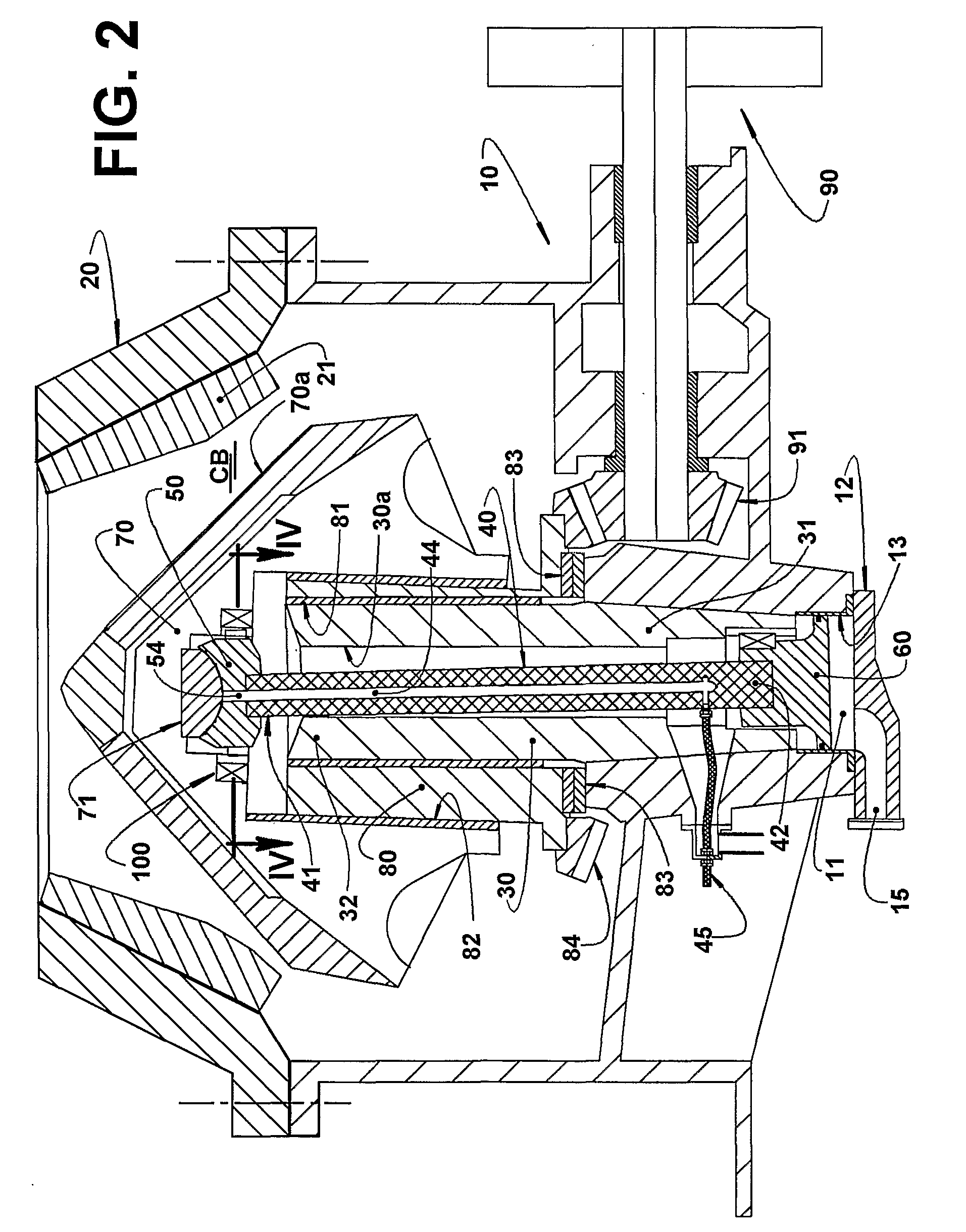
[0025]As illustrated in FIG. 2, the present crusher further comprises a vertically disposed tubular axle 30, having an axial through hole 30a and a lower end 31 fixed to the structure 10 and open to an upper end of a hydraulic cylinder 11, which is inferiorly formed in the structure 10 and has a lower end closed by a cover 12. The tubular axle 30 presents an upper end 32.

[0026]The hydraulic cylinder 11 has a lateral wall 13a generally defined by a removable cylindrical sleeve 13, internally lining said hydraulic cylinder 11. Inside the tubular axle 30 is provided a supporting rod 40 that has an upper end 41 carry...


PUM


Abstract

A conical crusher, comprising: an upper housing; a tubular axle lodging a supporting rod. Inside the upper housing is mounted a cone head being axially journalled onto a spherical bearing carried by an upper end of the supporting rod and said cone head being radially and eccentrically journalled around the tubular axle. The supporting rod has a lower end thereof fixed to a piston of a hydraulic cylinder in order to operate as a support means for the cone head and also as an actuator to vertically displace the cone head and adjust the opening of the crushing cavity and also as a protecting means, reducing the hydraulic pressure to prevent overloads. The proposed solution further provides a locking hub mechanism in the cone head.

Description

FIELD OF THE INVENTION[0001]The present invention refers, in general terms, to a conical crusher of the type comprising an upper housing in which interior operates a cone head driven in an eccentric oscillating motion around a fixed vertical tubular axle, said cone head being axially journalled at the upper end of a supporting rod located inside the tubular axle and which is axially and selectively displaceable in order to vary the opening of a crushing cavity defined between the cone head and the upper housing.[0002]The invention is particularly related to the means responsible for bearing and adjusting the position of the cone head in relation to the upper housing.PRIOR ART[0003]Different constructive solutions are known for supporting the cone head of a crusher of the type considered herein.[0004]One of the known solutions may be found schematically illustrated in FIG. 1 of the attached drawings, in which is represented a conical crusher comprising a structure 10 in which is supe...

Claims


Application Information

Patent Timeline
Patent Type & Authority Applications(United States)
IPC IPC(8): B02C15/10
CPCB02C2/047
Inventor NIKLEWSKI, ANDRZEJ
Owner METSO OUTOTEC (FINLAND) OY
Why Eureka
Try Eureka