
Method and apparatus for controlling power in an emulation system

Active Publication Date: 2008-10-30
CADENCE DESIGN SYST INC
View PDF26 Cites 11 Cited by
  • Summary
  • Abstract
  • Description
  • Claims
  • Application Information

AI Technical Summary

Benefits of technology

[0006]Method and apparatus for controlling power in an emulation system are described. One aspect of the invention relates to controlling power in an emulation system coupled to a host computer. A first interface is configured to receive requirement information for a logic module to be emulated from the host computer system. The requirement information includes at least one of a power requirement or a thermal requirement. A second interface is configured to receive measurement data from sensors in the emulation system. A controller is configured to control at least one of a synchronization system, a power regulation system, or a thermal system in the emulation system in response to the requirement information and the measurement data to reduce power load of the emulation system.
[0007]Another aspect of the invention relates to an emulation system. The emulation system includes an emulation engine. A synchronization module is configured to provide clock signals to the emulation engine. A communication module is provided. A cooling system is configured to cool the emulation engine. A power regulation system is configured to provide power to the emulation engine. A sensor system is configured to measure at least one of temperature or current. A control system is configured to receive requirement information for a logic module to be emulated from the communication module, receive measurement information from the sensor system, and control at least one of the synchronization system, the power regulation system, or the cooling system in response to the requirement information and the measurement data to reduce power load of the emulation system.

Problems solved by technology

This creates a barrier for some users, where the requirements of such specialized equipment are onerous.

Method used


Image

  • Method and apparatus for controlling power in an emulation system
  • Method and apparatus for controlling power in an emulation system
  • Method and apparatus for controlling power in an emulation system

Examples


Embodiment Construction

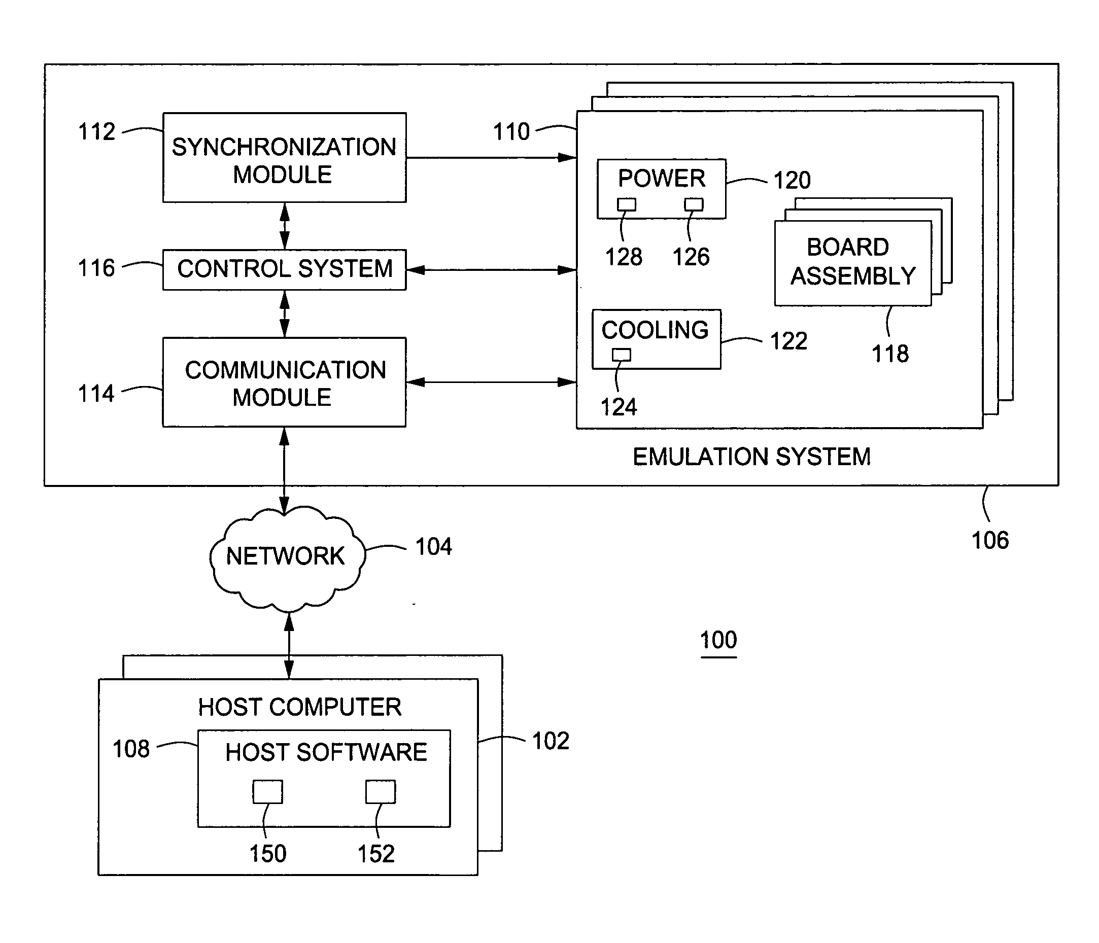
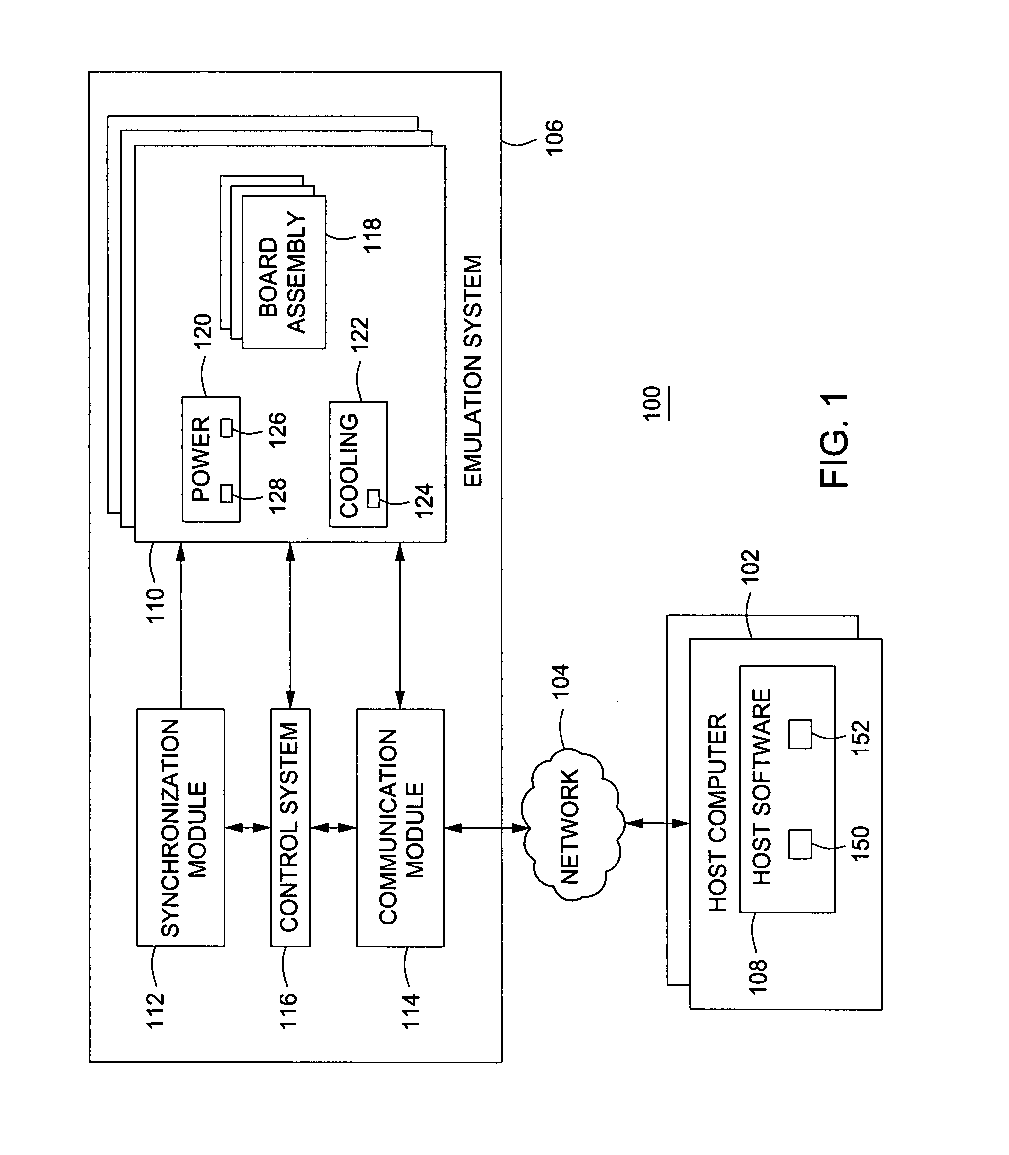
[0015]FIG. 1 is a block diagram depicting an exemplary embodiment of a circuit design testing system 100 in accordance with one or more aspects of the invention. The system 100 includes one or more host computer systems 102, a network 104, and an emulation system 106. Each of the computer systems 102 is configured for communication with the emulation system 106 via the network 104. The network 104 may comprise any type of computer network known in the art, such as an Ethernet network. Each of the computer systems 102 executes host software 108, which may provide one or more functions. The host software 108 may be used to configure the emulation system 106 to emulate a device and to establish an initial state of the emulated device by loading values into registers, latches, or other constructs. The host software 108 may be used to capture data from the emulation system 106 for purposes of monitoring. The host software 108 may also contain a compiler for translating a design specifica...


PUM


Abstract

Method and apparatus for controlling power in an emulation system are described. In one example, a first interface is configured to receive requirement information for a logic module to be emulated from a host computer system. The requirement information includes at least one of a power requirement or a thermal requirement. A second interface is configured to receive measurement data from sensors in the emulation system. A controller is configured to control at least one of a synchronization system, a power regulation system, or a thermal system in the emulation system in response to the requirement information and the measurement data to reduce power load of the emulation system.

Description

BACKGROUND OF THE INVENTION[0001]1. Field of the Invention[0002]Embodiments of the invention generally relate to circuit design emulation systems and, more specifically, to a method and apparatus for controlling power in an emulation system.[0003]2. Description of the Related Art[0004]The usefulness of software driven emulators has increased enormously with growth in the complexity of integrated circuits. Basically, an emulation engine operates to mimic a logical design of a set of one or more integrated circuit chips. Emulation engines typically contain an interconnected array of emulation processors. Each emulation processor can be programmed to evaluate logic functions. The program-driven processors operate together as an interconnected unit, emulating an entire desired logic design. As integrated circuit designs grow in size, more emulation processors are required to accomplish the emulation task.[0005]Due to the increasing number of emulation processors, the power and cooling r...

Claims


Application Information

Patent Timeline
IPC IPC(8): G06F9/445
CPCG06F1/206G06F1/3203G06F1/3296G06F2200/201Y02B60/1275Y02B60/1285Y02D10/00
Inventor POPLACK, MITCHELL GRANTBEAUSOLEIL, WILLIAM F.TOMASSETTI, N. JAMESTUNG, TUNG-SUN
Owner CADENCE DESIGN SYST INC
Learn More