
Reformer and fuel cell system incorporating the same

a fuel cell and reformer technology, applied in the direction of ignition automatic control, sustainable manufacturing/processing, instruments, etc., can solve the problems of device cost rise, unstable combustion, and out of combustion section, and achieve the effect of low cost and reliable judging

Inactive Publication Date: 2008-10-30
TOYOTA JIDOSHA KK
View PDF19 Cites 8 Cited by
  • Summary
  • Abstract
  • Description
  • Claims
  • Application Information

AI Technical Summary

Benefits of technology

[0011]Accordingly, it is a primary object of the present invention to provide an improved reformer capable of reliably judging that a combustion section is likely to go out, at a low cost and also capable of adjusting the combustion section to an optimum combustion state.
[0012]Another object of the present invention is to provide an improved fuel system incorporating the reformer of the character set forth above, so that the efficiency in electric power generation can be enhanced.
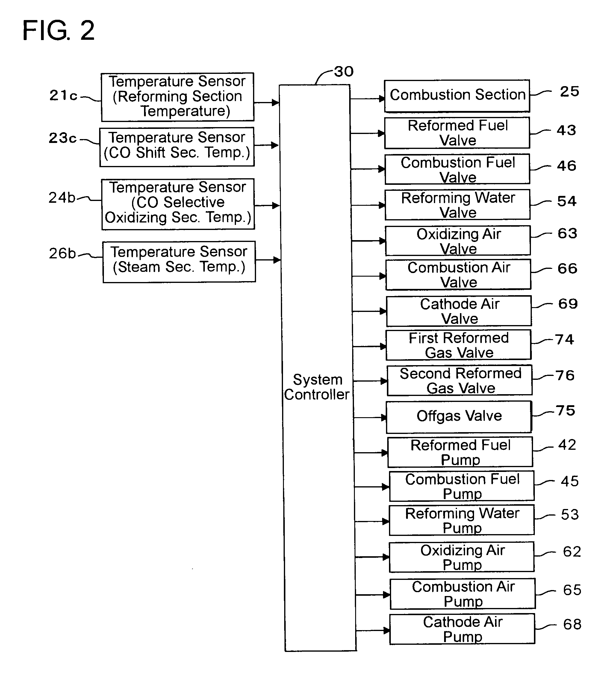
[0014]With this construction, the supply quantity changing means changes the supply quantity of at least either one of combustible gas and combustion oxidizing gas supplied to the combustion section, the combustion state change detecting means detects a change which is caused in the combustion state of the combustion section as a result that the supply quantity is changed by the supply quantity changing means, based on the detection result from the combustion state detecting means, and the combustion state checking means checks the combustion state of the combustion section which arose before the change by the supply quantity changing means, based on the detection result from the combustion state change detecting means. Thus, it becomes possible to change the supply quantity of at least either one of combustible gas and combustion oxidizing gas supplied to the combustion section. In addition, since the change in the combustion state of the combustion section resulting from the change in the supply quantity can be detected based on the detection result from the combustion state detecting means, it also becomes possible to check the combustion state of the combustion section which arose before the change by the supply quantity changing means, based on the detection result. That is, insofar as the supply means for combustible gas and combustion oxidizing gas and the combustion state detecting means operate correctly, it can be realized to check the combustion state of the combustion section which arose before the change by the supply quantity changing means. Accordingly, without using expensive sensors, it becomes possible to detect the state of the combustion section being likely to go out, reliably at a low cost.
[0016]Since the fuel cell system with this construction is provided with the reformer which is capable of reliably detecting at a low cost the state of the combustion section being likely to go out, it is possible to make the entire system low in cost and nevertheless, to reliably detect the state of the combustion section being likely to go out. As a consequence, the efficiency of the fuel cell system in electric power generation can be enhanced with the reformer operating in an optimum combustion state.

Problems solved by technology

However, in the reformer described in the first mentioned Japanese application, when the air-fuel ratio is shifted to the lower side due to detection errors in the raw fuel flow sensor 11 or the air flow sensor 13, it is likely to occur that the combustion section goes out, and thus, the combustion is apt to become unstable.
Further, the use of the flow sensors which are generally more expensive than temperature sensors may cause the device to rise in cost.
However, because the combustion state in each of the reformers is judged in dependence on the data from the various detecting means, there is a risk that the combustion may be erroneously judged due to detection errors in the detecting means.

Method used


Image

  • Reformer and fuel cell system incorporating the same
  • Reformer and fuel cell system incorporating the same
  • Reformer and fuel cell system incorporating the same

Examples


Embodiment Construction

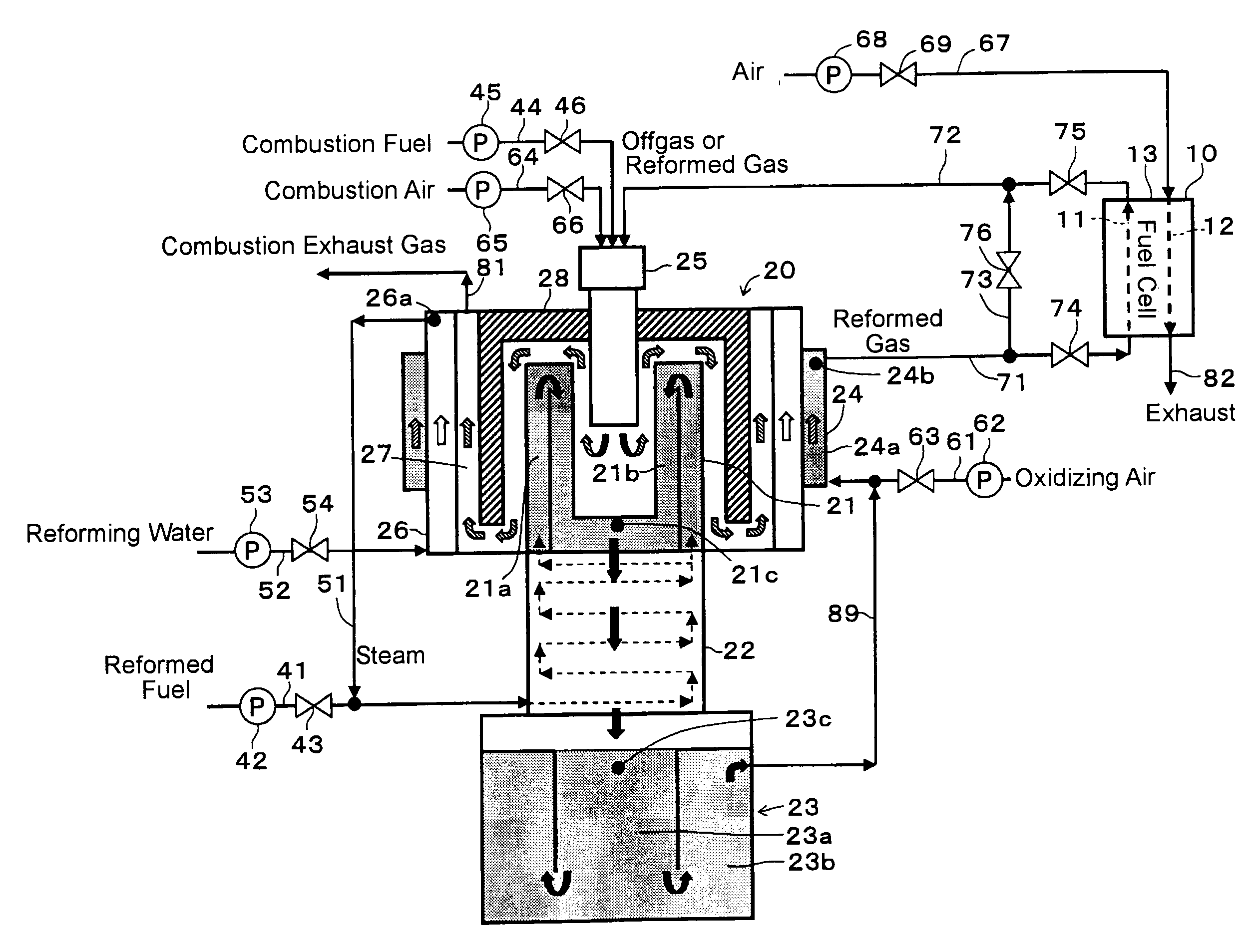
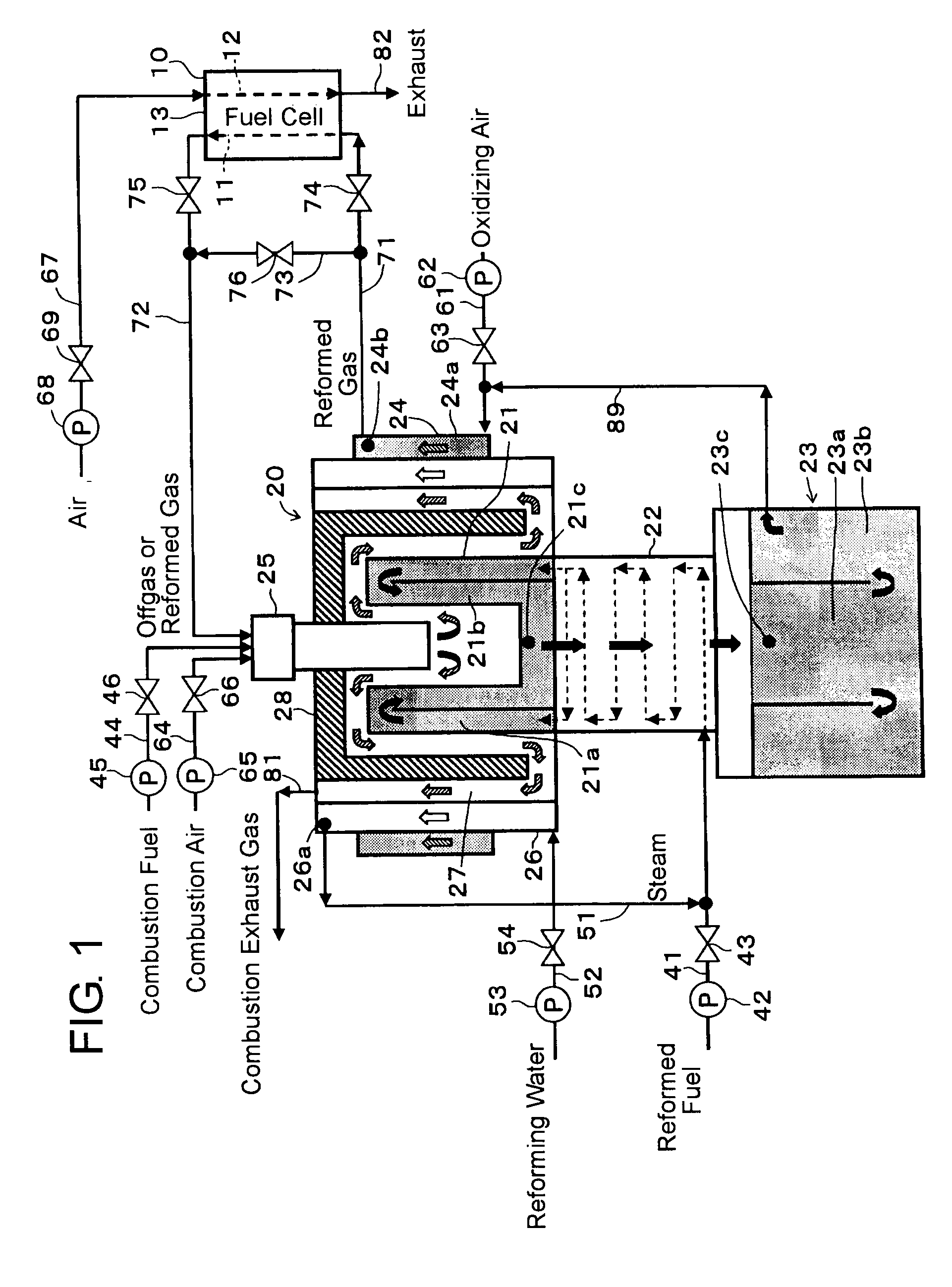
[0024]Hereafter, a fuel cell system incorporating a reformer in one embodiment according to the present invention will be described with reference to the drawings. FIG. 1 is a schematic view showing the outline of the fuel cell system. The fuel cell system is provided with a fuel cell 10 and a reformer 20 for generating reformed gas (fuel gas) containing hydrogen gas needed for the fuel cell 10.

[0025]The fuel cell 10 is provided with a fuel pole 11, an air pole 12 as an oxidizing agent or oxidizer pole, and an electrolyte 13 interposed between both of the poles 11 and 12. The fuel cell 10 is operable to generate electric power by using reformed gas supplied to the fuel pole 11 and air (cathode gas) as oxidizing gas supplied to the air pole 12. Instead of air, there may be supplied gas which is air enriched with oxygen.

[0026]The reformer 20 reforms reformed fuel (i.e., raw fuel to be reformed) with steam and supplies the fuel cell 10 with hydrogen-rich reformed gas. The reformer 20 i...


PUM

PropertyMeasurementUnit
electric power quantityaaaaaaaaaa
output electric power quantityaaaaaaaaaa
combustion stateaaaaaaaaaa

Abstract

A controller for a reformer includes supply quantity changing means for changing the supply quantity of at least either one of combustible gas and combustion oxidizing gas supplied to a combustion section, a combustion state change detecting means for detecting a change which is caused in the combustion state of the combustion section as a result that the change of the supply quantity is brought by the supply quantity changing means, based on a detection result from the combustion state detecting means, and combustion state checking means for checking the combustion state which arose at the combustion section before the change brought by the supply quantity changing means, based on a detection result from the combustion state change detecting means. Thus, the gone-out state of the combustion section can be reliably judged with the construction of a low cost, and the combustion state of the combustion section in the reformer of a fuel cell system can be adjusted to an optimum combustion state.

Description

INCORPORATION BY REFERENCE[0001]This application is based on and claims priority under 35 U.S.C. 119 with respect to Japanese Patent Application No. 2007-116810 filed on Apr. 26, 2007, the entire content of which is incorporated herein by reference.BACKGROUND OF THE INVENTION[0002]1. Field of the Invention[0003]The present invention relates to a reformer and a fuel cell system incorporating the same for generating electric power.[0004]2. Discussion of the Related Art[0005]As one form of reformers, there has been known a reformer which is described in Japanese unexamined, published patent application No. 2001-165431. As shown in FIG. 1 of the Japanese application, the reformer is provided with a raw fuel flow sensor 11 on a raw fuel supply passage 2 for supplying raw fuel to a reformer 1, and a feedback control is performed by a raw fuel flow controller FC1 regarding the opening degree of a raw fuel flow control valve 12. Further, an air flow sensor 13 is provided on an air supply pa...

Claims


Application Information

Patent Timeline
Patent Type & Authority Applications(United States)
IPC IPC(8): H01M8/06G05B11/00B01J8/00C01B3/24
CPCB01J8/025B01J8/0278B01J8/0285B01J2208/00061B01J2208/00168B01J2208/00309B01J2208/00504B01J2208/0053B01J2208/00601B01J2219/002B01J2219/00211B01J2219/00231C01B3/384C01B3/48C01B2203/0233C01B2203/0283C01B2203/044C01B2203/047C01B2203/066C01B2203/0816C01B2203/0822C01B2203/0827C01B2203/1619C01B2203/1685C01B2203/1695H01M8/0618H01M8/0662Y02E60/50Y02P20/10
Inventor TAKADA, KAZUMASATOYONAGA, NORIHIKO
Owner TOYOTA JIDOSHA KK
Learn More