
High voltage power controlling apparatus of image forming apparatus and method thereof

a technology of power controlling apparatus and image forming apparatus, which is applied in the direction of electrographic process apparatus, instruments, electrographic process apparatus, etc., can solve the problems of high material cost of the components constituting the bulkiness of the image forming apparatus, and achieve the effect of reducing bulkiness and manufacturing costs of the image forming apparatus, and simplifying circuit structur

Active Publication Date: 2008-10-30
HEWLETT PACKARD DEV CO LP
View PDF2 Cites 6 Cited by
  • Summary
  • Abstract
  • Description
  • Claims
  • Application Information

AI Technical Summary

Benefits of technology

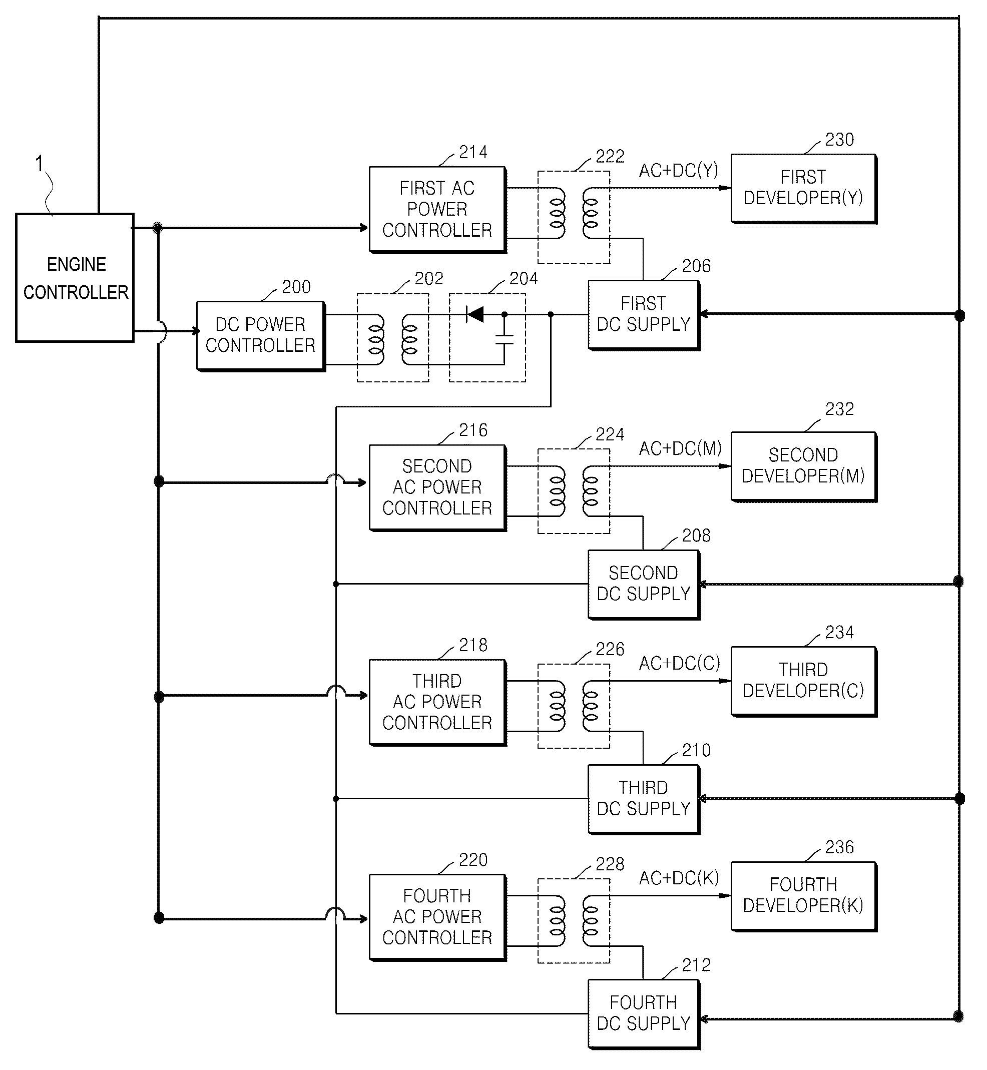
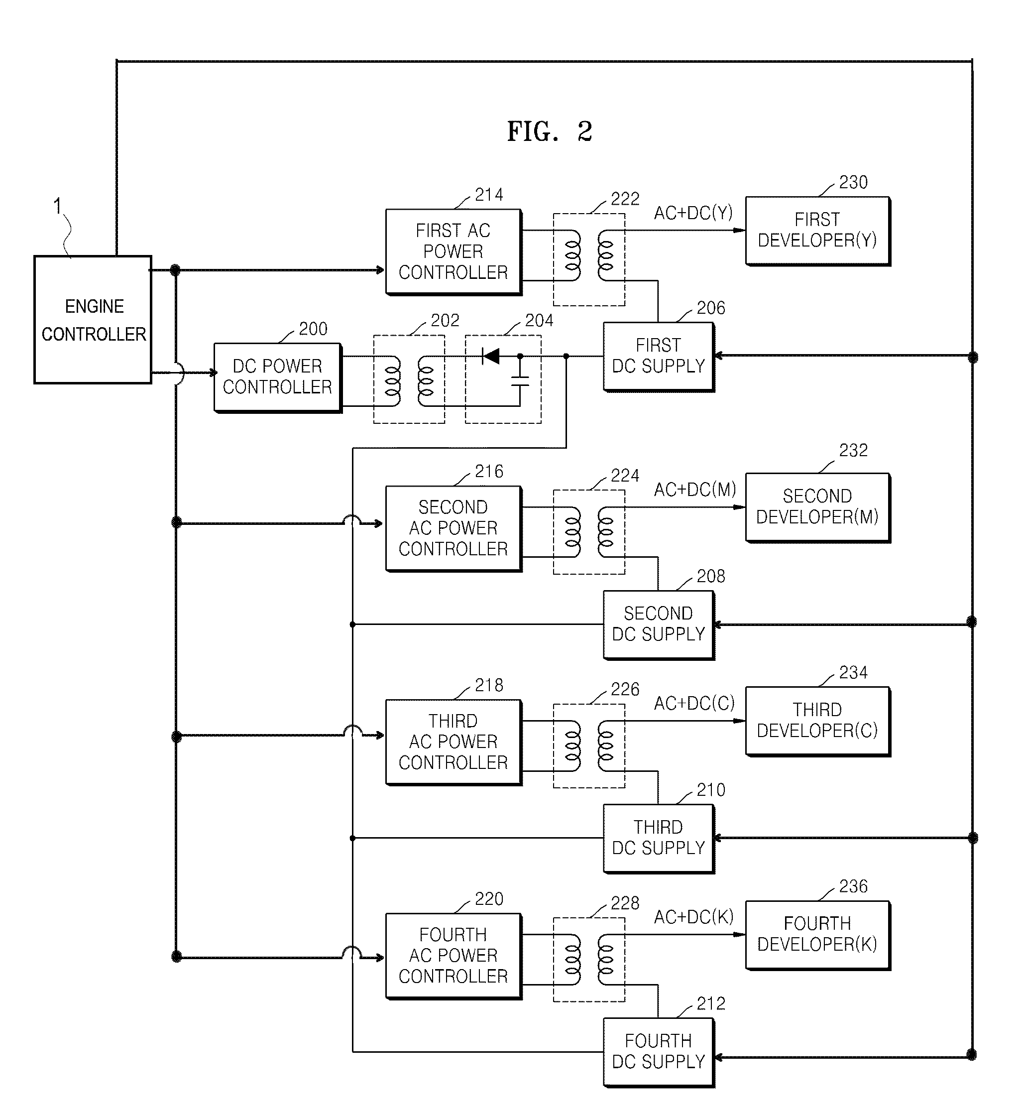
[0008]The present general inventive concept provides a high voltage power controlling apparatus of an image forming apparatus having a simplified circuit structure, which controls an overlapping power of an alternating current (AC) and a direct current (DC) that is supplied to each of yellow (Y), cyan (C), magenta (M), and black (K) developers, thereby reducing a bulkiness and manufacturing costs of the image forming apparatus, and a method thereof.
[0017]Each of the DC supplies may further include a capacitor to smooth the ripples of the DC power having the adjusted power level.

Problems solved by technology

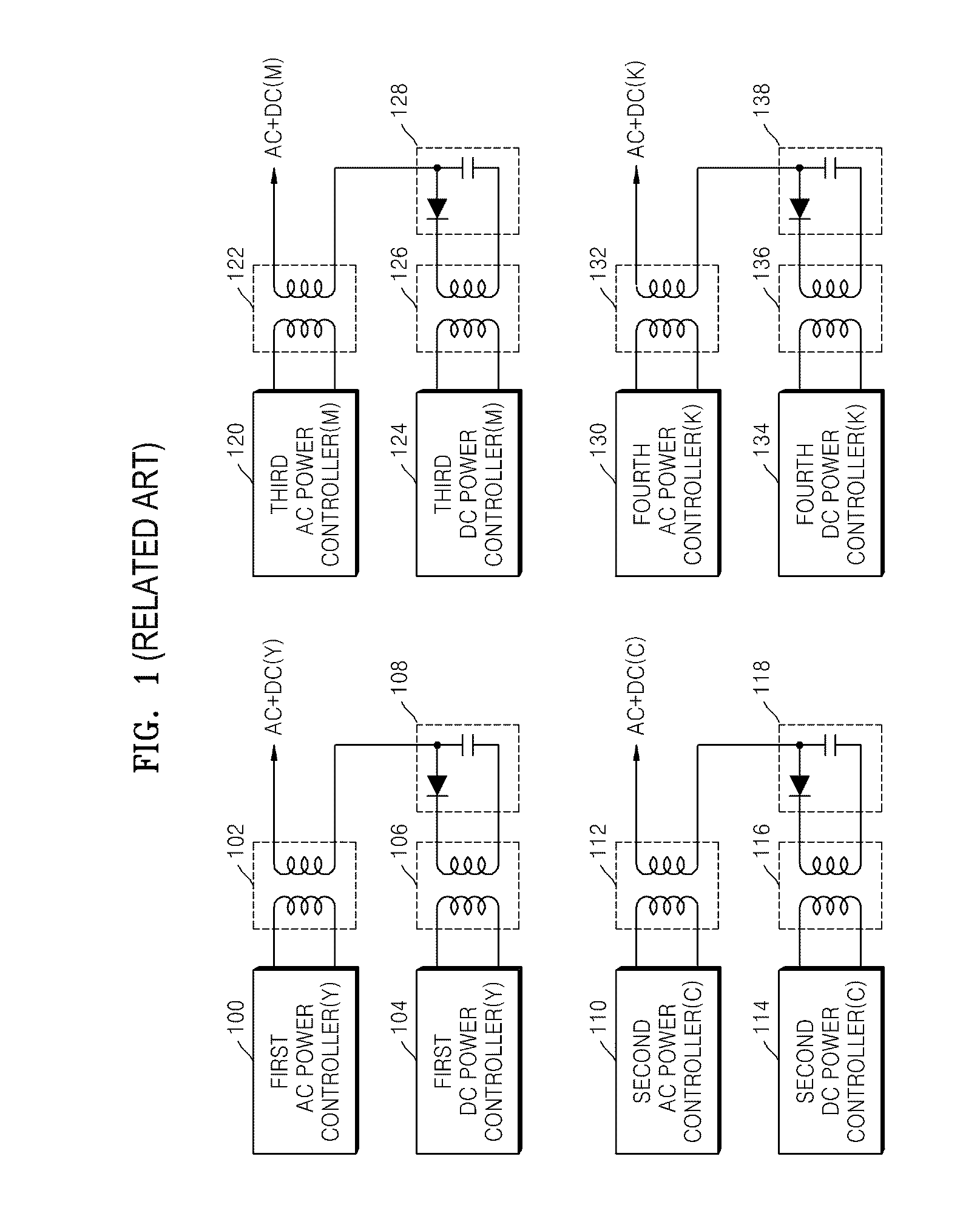
As a result, the image forming apparatus becomes bulky and the material costs for the components constituting the image forming apparatus are high.

Method used


Image

  • High voltage power controlling apparatus of image forming apparatus and method thereof
  • High voltage power controlling apparatus of image forming apparatus and method thereof
  • High voltage power controlling apparatus of image forming apparatus and method thereof

Examples


Embodiment Construction

[0034]Reference will now be made in detail to the embodiments of the present general inventive concept, examples of which are illustrated in the accompanying drawings, wherein like reference numerals refer to the like elements throughout. The embodiments are described below in order to explain the present general inventive concept by referring to the figures.

[0035]FIG. 2 is a circuit diagram illustrating a high voltage power controlling apparatus of an image forming apparatus according to an embodiment of the present general inventive concept. Referring to FIG. 2, the high voltage power controlling apparatus includes a direct current (DC) power controller 200, a first voltage transformer 202, a rectifier 204, first, second, third, and fourth DC supplies 206, 208, 210, and 212, first through fourth alternating current (AC) power controllers 214, 216, 218, and 220, and second, third, fourth, and fifth voltage transformers 222, 224, 226, and 228. The high voltage power controlling appa...


PUM


Abstract

A high voltage power controlling apparatus of an image forming apparatus including a DC (direct current) power controller to convert and output a first PWM (pulse width modulation) signal provided from an engine controller into a switching waveform signal, a first voltage transformer to transform the switching waveform signal output from the DC power controller, a rectifier to rectify output power transformed by the first voltage transformer into DC power, first through N (where N is a positive integer greater than one) DC supplies to adjust and output the DC power rectified by the rectifier such that the DC power is adjusted to a predetermined level, first through N AC (alternating current) power controllers to convert and output a second PWM signal provided from the engine controller into switching waveform signals, and second through N+1 voltage transformer to transform the switching waveform signals output from the first through N AC power controllers, to overlap the transformed powers with the DC powers having predetermined levels of the first through N DC supplies, and to output the overlapped powers to first through N developers, respectively.

Description

CROSS-REFERENCE TO RELATED APPLICATIONS[0001]This application claims priority under 35 U.S.C. 119(a) from Korean Patent Application No. 10-2007-0040056, filed on Apr. 24, 2007, in the Korean Intellectual Property Office, the disclosure of which is incorporated herein in its entirety by reference.BACKGROUND OF THE INVENTION[0002]1. Field of the Invention[0003]The present general inventive concept relates to a high voltage power controlling apparatus of an image forming apparatus which reduces a number of voltage transformers that supply direct current (DC) power in a high voltage power supply which is applied to a laser printer or a laser multi-function peripheral device, so as to reduce both a size of the image forming apparatus and material costs, and a method thereof.[0004]2. Description of the Related Art[0005]FIG. 1 is a circuit diagram of a conventional high voltage power controlling apparatus supplied to each cyan (C), magenta (M), yellow (Y), and black (K) developer. Referrin...

Claims


Application Information

Patent Timeline
Patent Type & Authority Applications(United States)
IPC IPC(8): H02J1/00H02J3/00
CPCG03G15/065G03G15/80G03G15/08G03G21/14H02M3/33507
Inventor CHO, JONG-HWAOH, CHUL-WOO
Owner HEWLETT PACKARD DEV CO LP
Learn More