Snap Ring Pliers

a technology of snap pliers and pliers, which is applied in the direction of pliers, metal-working hand tools, manufacturing tools, etc., can solve the problems of not providing the optimum 90° angle of engagement between the tips and the retaining ring aperture, and achieve the effect of constricting the internal retaining ring

Inactive Publication Date: 2008-10-30
DUFFY SEAMUS
View PDF22 Cites 17 Cited by
  • Summary
  • Abstract
  • Description
  • Claims
  • Application Information

AI Technical Summary

Benefits of technology

[0014]When operating external retaining rings the jaw portion is threepoint mounted via a latching bolt or screw portion fitted through the axis joint and central axis throughbores and onto the two actuating pins on the handle portion levered end, engaging similarly centrally equidistant cross lever operating holes. The screw portion preferably consists of a pivot bolt having a plurality of grooves fitted parallel along the length of its male thread. The central axis throughbore has similar placed grooves substantially providing a female mirror of the pivot bolt male threaded portion, such that when the pivot bolt is entered into the central axis throughbore it's threads can easily move in or out of groves therein, whereas when the pivot bolt is rotated within the axis joint throughbore their threads can mesh and conveniently lock the jaw portion and the handle portion together. As the handle portion is operated the parallel jaws are forced open by the action of the actuating pins rotating the cross levers attached to the parallel jaws by the lever pivots. The reverse cone operating tips at the end of the parallel jaws within the retaining ring apertures opening the external retaining ring. When the jaw portion is fitted to the opposite side of the handle portion engaging the actuating pins fitted to the handle levering end, operating the handle portion forces the parallel jaws closed, closing as required the worked internal retaining ring. If required a resilient member fitted between the handles ensures the levering end of the handles remain open and the levered end remains closed when at rest. By virtue of the reverse cone tips and their parallel operation the retaining ring is effectively locked onto the operating tips during it's operation allowing the retaining ring to be robustly positioned with safety and ease.
[0015]In summary there is provided parallel jaw locking snap ring pliers wherein the operating tips remain substantially at the optimum 90° angle of engagement throughout their use. The operating tips move in a parallel way relative to each other enabling the operating tips to always be at the optimum angle. The operating tips are preferably formed as part of the parallel jaws although it is understood that the preferably reverse cone operating tips that engage the retaining ring apertures to operate the retaining rings can be interchangeable if required. The jaw portion can quickly and conveniently be fitted or removed from the handle portion by the utilisation of the pivot bolt threaded portion having parallel grooves which are the same or less width than the corresponding grooved threads within the central axis throughbore, allowing the pivot bolt threaded portion to slide in or out of position within the central axis throughbore, yet requires less than quarter of a turn of the pivot bolt to lock the two portions together.
[0016]The jaw portion can be detached from the handle portion and rotated in order to engage differing operating tips for example angled or different tip sizes. The engagement of the jaw portion onto the actuating pins fitted to the handle portion levered end allows the pliers to be operated to distend external retaining rings. The further engagement of the jaw portion onto the levering end actuating pins fitted to the reverse side of the handle portion allows the pliers to be operated to constrict internal retaining rings.

Problems solved by technology

As the pliers are used the tips move in an arc, thereby the rotation of the tip within the positioning groove or slot during operation does not provide the optimum 90° angle of engagement between the tips and retaining ring apertures especially the straight tips.
In some circumstances the angle is severe enough to cause disengagement.

Method used


Image

  • Snap Ring Pliers
  • Snap Ring Pliers
  • Snap Ring Pliers

Examples


Embodiment Construction

[0019]Embodiments of the present invention will now be described by way of example, with reference to the accompanying drawings in which:

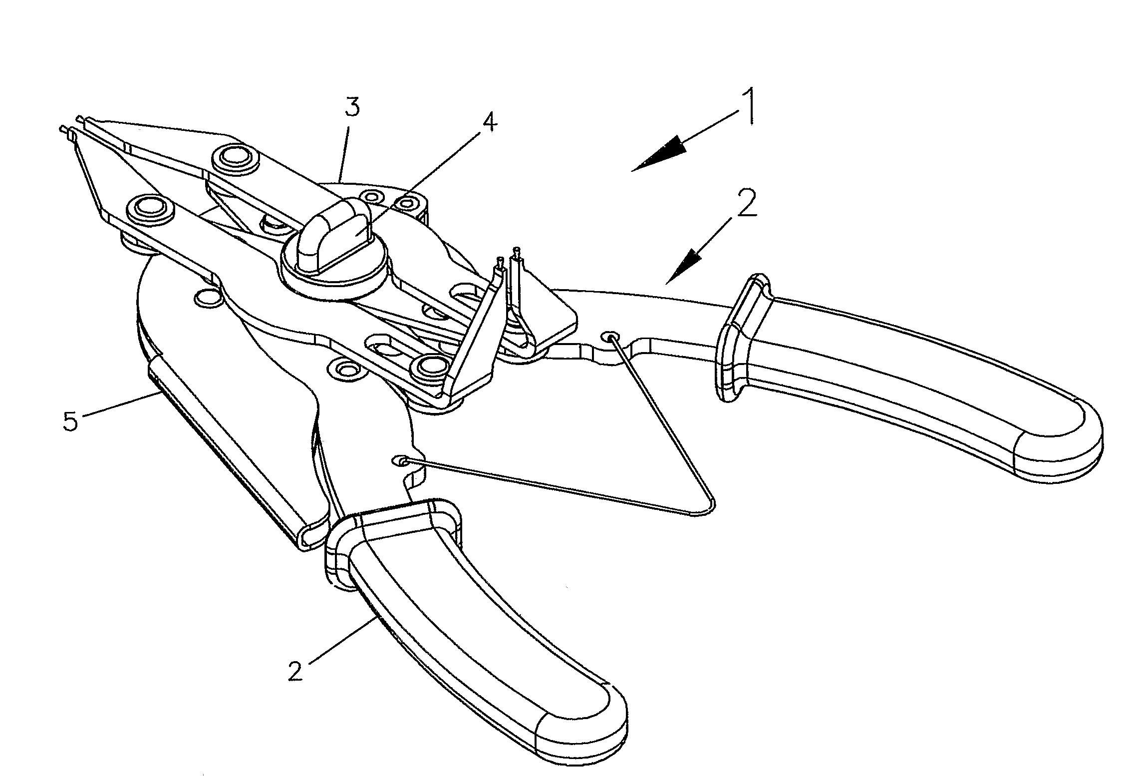
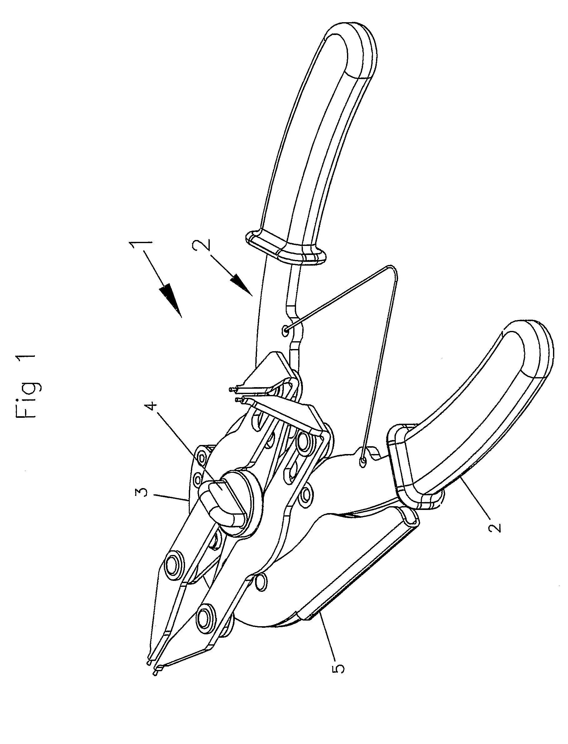
[0020]FIG. 1 is a perspective view of the parallel jaw locking snap ring pliers.

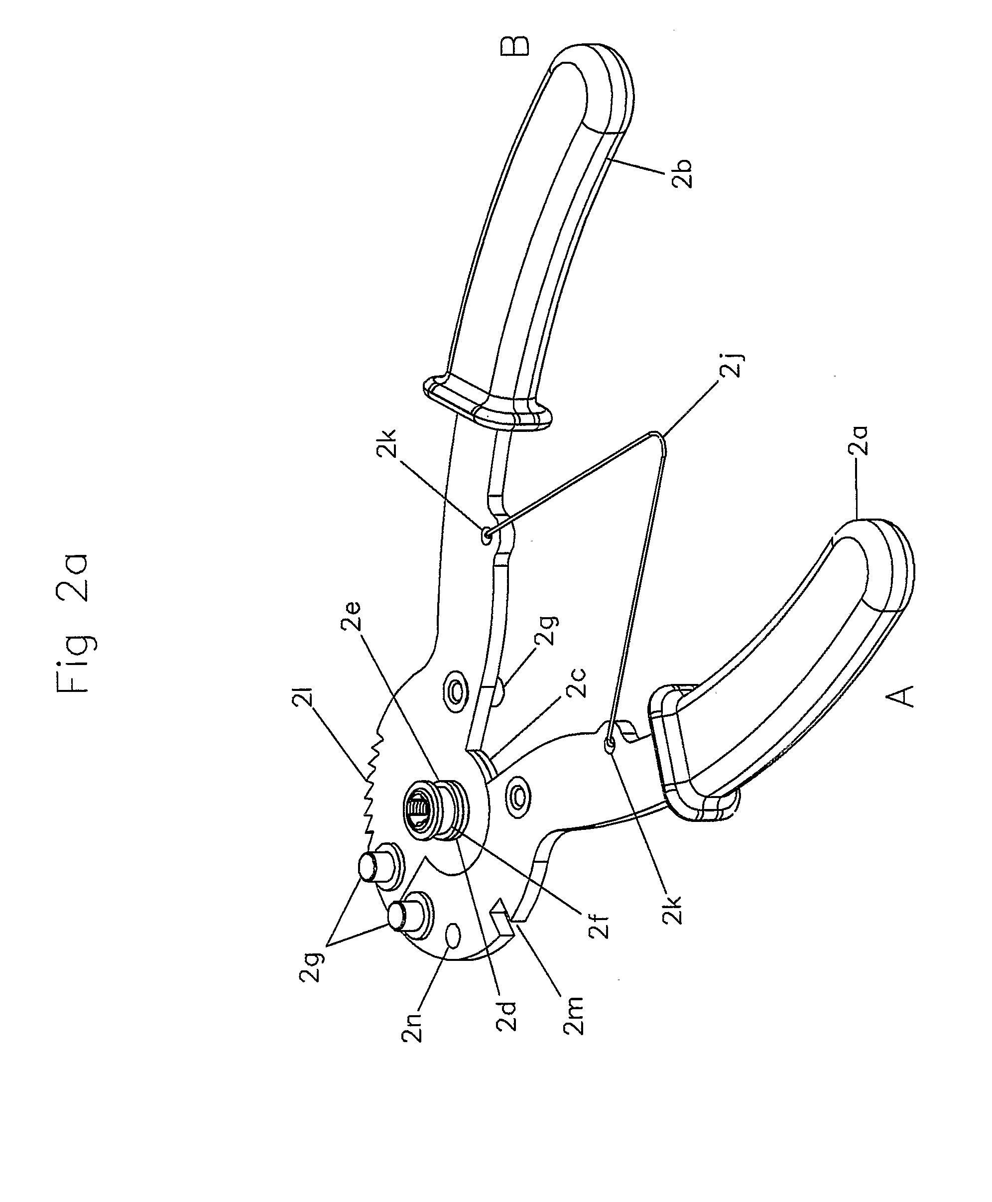
[0021]FIG. 2a is a perspective view of the handle portion of the snap ring pliers.

[0022]FIG. 2b is a perspective view of the jaw portion of the snap ring pliers illustrating in particular the reverse cone operating tips and the pivot bolt.

[0023]FIG. 2c is a perspective view of the locking portion of the snap ring pliers.

[0024]FIG. 3a is a plan view -of the parallel jaw locking snap ring pliers at rest less the locking portion. The jaw portion fitted to the actuating pins on the levered end of the handle portion. The reverse cone operating tips being highlighted.

[0025]FIG. 3b is a plan view of the parallel jaw locking snap ring pliers less the locking portion in an operated position, the actuating pins on the levered end actuating the jaw portion.

[0026]FIG. 3c is a plan ...


PUM


Abstract

The jaw portion comprises cross levers centrally connected by a rotatable central axis with a throughbore and outwardly connected by lever pivots to parallel jaws (within clots at one end) with tapered operating tips at either end.

Description

FIELD OF THE INVENTION[0001]This invention relates to circlip pliers or snap ring pliers which are well known for the removal or replacement of circlips (in the U.S.A referred to as “snap rings”) into their retaining grooves. There are two main types; internal and external. The internal type reduces the circumference of the circlip; the external type expanding the circlip circumference.BACKGROUND OF THE INVENTION[0002]The known types of snap ring pliers work in a similar fashion to scissors. The handles pivoting around a fulcrum in order to lever the circlip via the levered end operating prongs in the required direction. Most circlips consist of an open ring of thin spring steel with a hole at the open ends of the ring. The holes are for the engagement of the operating prongs of the snap ring pliers. Dependant upon the orientation of the levered end operating prongs the circlip either opens or closes as the snap ring plier handles are operated. The operating prongs can be straight o...

Claims


Application Information

Patent Timeline
Patent Type & Authority Applications(United States)
IPC IPC(8): B25B7/12B25B7/02B25B7/14B25B7/18B25B27/14B25B27/20
CPCB25B7/12B25B7/14B25B7/18B25B27/205
Inventor DUFFY, SEAMUS
Owner DUFFY SEAMUS
Why Eureka
Try Eureka