
Virtual computer system

Inactive Publication Date: 2008-10-23
HITACHI LTD
View PDF5 Cites 60 Cited by
  • Summary
  • Abstract
  • Description
  • Claims
  • Application Information

AI Technical Summary

Benefits of technology

[0007]A virtual machine system, in which a plurality of virtual machines operate on a real machine under control of a virtual machine controller, comprises: an actual device used as a dedicated device only by one user virtual machine; and an actual device commonly used as a shared device by a plurality of user virtual machines via a control virtual machine, wherein each of the user virtual machines and the control virtual machine include a fault monito

Problems solved by technology

Firstly, in monitoring a failure with respect to a shared PCI device (i.e., one real PCI device which a plurality of virtual machines use), when a failure has occurred in the real PCI device, a device driver of an OS operating on the respective virtual machines that use the shared PCI device generates an event of the failure, so that a failure monitoring application operating on the respective virtual machines detects the failure, which is consequently notified as a plurality of failures to a system administrator of the virtual machine system. Actually, the above-described failure needs to be reported as the failure of one real PCI device.
Secondly, in monitoring a failure with respect to a virtual PCI device which a hypervisor not having a real PCI device virtually creates, when a failure has occurred in the virtual PCI device due to an anomaly in processing the virtual PCI device by the hypervisor, a device driver of an OS operating on a virtual machine that is currently used in the virtual PCI device detects the failure by means of a failure monitoring application in order to generate an event of the failure, which is consequently notified as the occurrence of the PCI device failure to a system administrator of the virtual machine system. Actually, the above-described failure needs to be reported the an anomaly of the hypervisor.

Method used


Image

  • Virtual computer system
  • Virtual computer system
  • Virtual computer system

Examples


Embodiment Construction

[0014]Hereinafter, an embodiment in practicing the present invention is specifically described using the accompanying drawings.

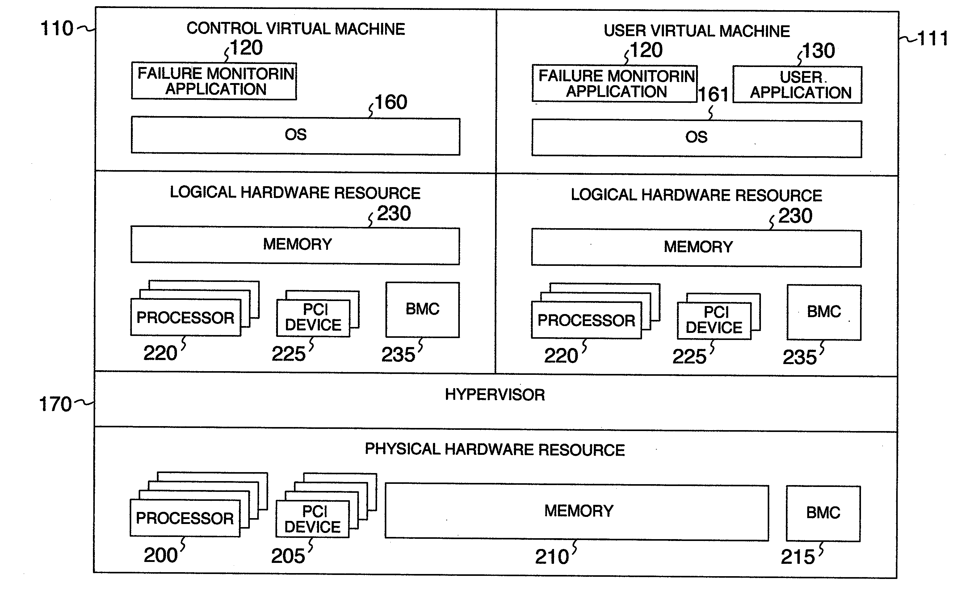
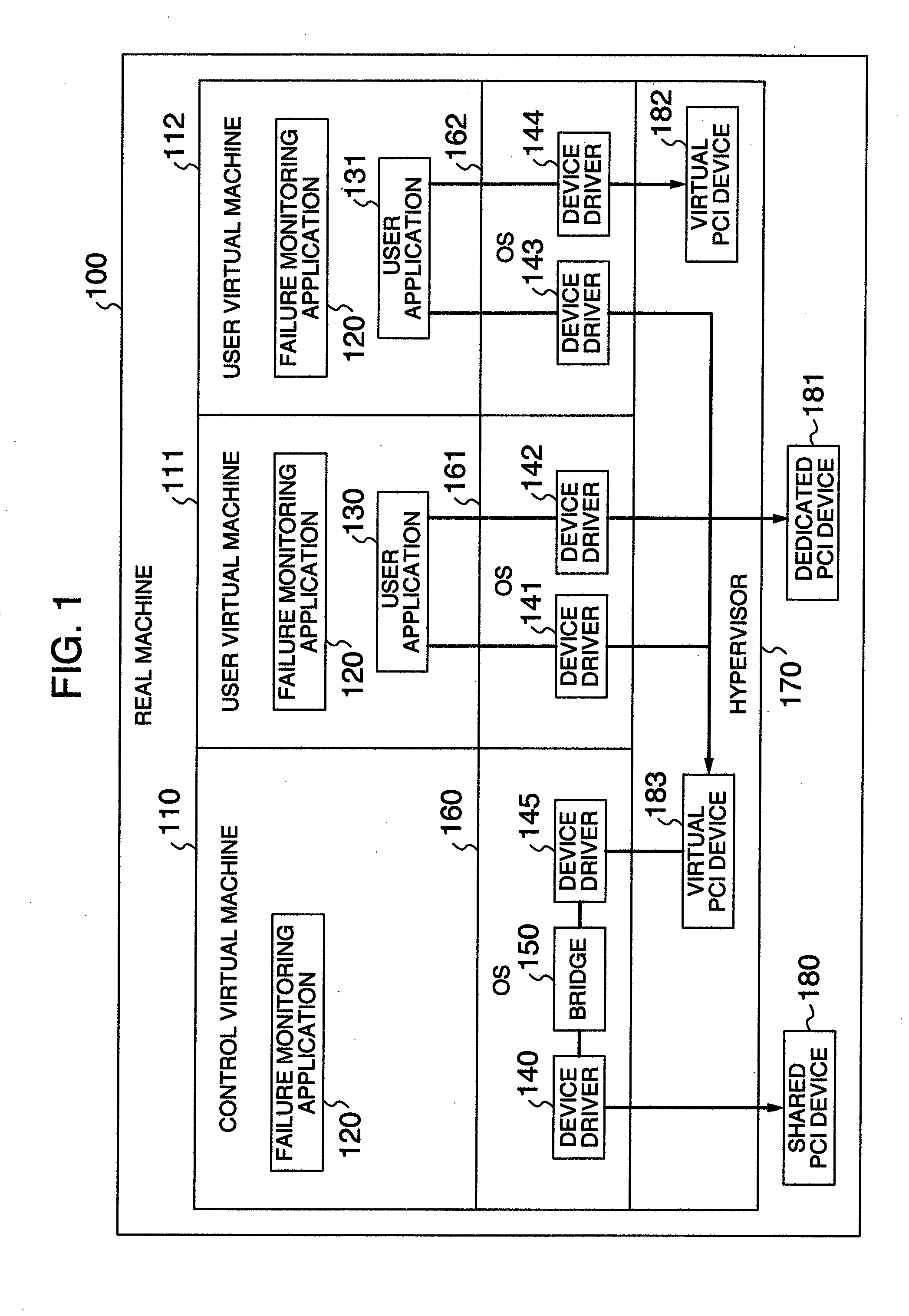
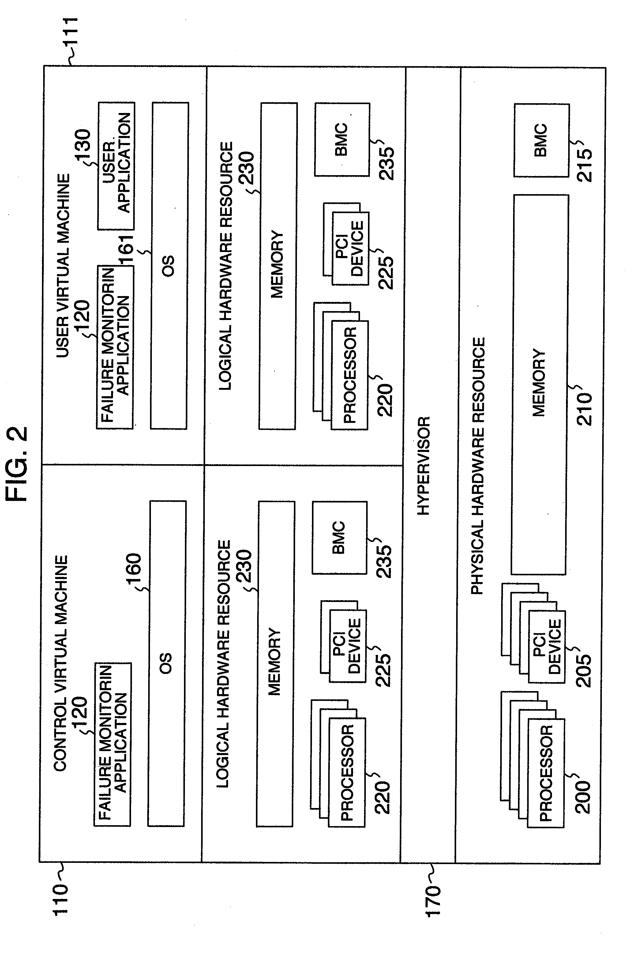
[0015]FIG. 1 is a system configuration view showing an embodiment of the present invention. On a real machine (100), a hypervisor (virtual machine control program) (170) runs to create virtual machines (110), (111), and (112). Among these, the virtual machine (110) is a control virtual machine that is used in order to control a virtual machine system, and the presence of this virtual machine is obscured with respect to a user of the virtual machine system.

[0016]The virtual machines (111) and (112) are user virtual machines which a user can use. OSs (160), (161), and (162) run on the respective virtual machines, and user applications (130) and (131) are running on the user virtual machines (111) and (112). The user applications (130) and (131) access PCI devices using device drivers (141), (142), (143), and (144).

[0017]A dedicated PCI device (181) is a real P...


PUM


Abstract

To improve the maintainability of a virtual machine system, there is provided a mechanism capable of appropriately reporting a failure that occurs in a dedicated PCI device, in a shared PCI device, or in a virtual PCI device. A device for transferring PCI device configuration information between a failure monitoring application and a hypervisor that monitors a PCI device failure is prepared, and the failure monitoring application is operated in a user virtual machine and in a control virtual machine. Based on the above-described PCI device configuration information, the failure monitoring application operating in the user virtual machine monitors a dedicated PCI device failure and a virtual PCI device failure, and the failure monitoring application operating in the control virtual machine monitors a shared PCI device failure, respectively, thereby appropriately reporting a failure of the dedicated PCI device, the shared PCI device, or the virtual PCI device without duplication.

Description

BACKGROUND OF THE INVENTION[0001]The present invention relates to a method for monitoring a device failure of a computing system, and in particular, relates to a technique for monitoring a PCI device failure in a virtual machine system in which a plurality of virtual machines run on a real machine.[0002]In order to improve the maintainability of the computing system, it is necessary to correctly notify a system administrator of an area where a failure has occurred. JP-A-2000-222247 describes a method for monitoring a failure, in which a failure monitoring application periodically monitors an event occurring on an operating system (OS) and issues a warning of occurrence of a fault when it has detected an event indicative of the occurrence of a fault.SUMMARY OF THE INVENTION[0003]However, the method for monitoring a failure, wherein in a virtual machine system, in which a plurality of virtual machines run on a real machine, the above-described method for monitoring an event is used on...

Claims


Application Information

Patent Timeline
IPC IPC(8): G06F11/30
CPCG06F11/0712G06F11/0745G06F11/0775
Inventor YAMAMOTO, MITSUO
Owner HITACHI LTD
Learn More