Double locked hip implant

Inactive Publication Date: 2008-10-23
FERNANDEZ DELLOCA ALBERTO ANGEL
View PDF8 Cites 18 Cited by
  • Summary
  • Abstract
  • Description
  • Claims
  • Application Information

AI Technical Summary

Benefits of technology

[0008]Is therefore an object of the present invention to provide a novel orthopedic device for minimal invasive treatment of proximal femoral fractures, which combines the advantages of intramedullary nails in fracture fixation with the benefits of sliding hip screws on fracture reduction.
[0009]Another object of the present invention is to provide a system rotationally stable that inhibits rotation of the femoral head on the axis of the hip implants.
[0010]Yet another object of the present invention is to teach an easy insertion technique of a double screw system that implies less surgical time without consuming a large area inside the femoral neck, by inserting both hip implants close together, making the insertion technique less demanding for the surgeon. The present invention by being an easy and straightforward procedure for the treatment of proximal femoral fractures, makes bone fixation of intramedullary nails simple and fast overcoming one of the most important subject of matter of actual surgery, time shortening.

Problems solved by technology

This device, while permitting an adequate fixation and rotational control of the fracture, does not allow sliding and therefore fails to provide compression of the proximal bone fragments against each other.
As a result, bone contact was insufficient to support the patient's weight, resulting in an increased risk of bending or breaking of the implanted hip nail.
This fact, together with the shape of the hip nail, determinate too much pressure over the femoral neck and head bone tissue, that could lead the implant to cut through the cancellous tissue of the femoral neck or head in a condition known as “cut out”, causing the nail to pierce the surface of the femoral neck or head, or at least to loose the proper alignment of the bone fracture.
However, this type of implant lacks rotational control, allowing rotation of the femoral head around the hip screw.
However, as these hip screws are not attached to each other, they have the disadvantage of permitting independent rotation around the screw axis and sliding of each screw, which may cause one screw to rotate around its own axis or slide respect to the other screw.

Method used


Image

  • Double locked hip implant
  • Double locked hip implant
  • Double locked hip implant

Examples


first embodiment

[0043]Hereinafter, a device to immobilize bone fragments of fractures occurring in the proximal region of the femur, according to the present invention, will be explained with reference to FIGS. 1-8.

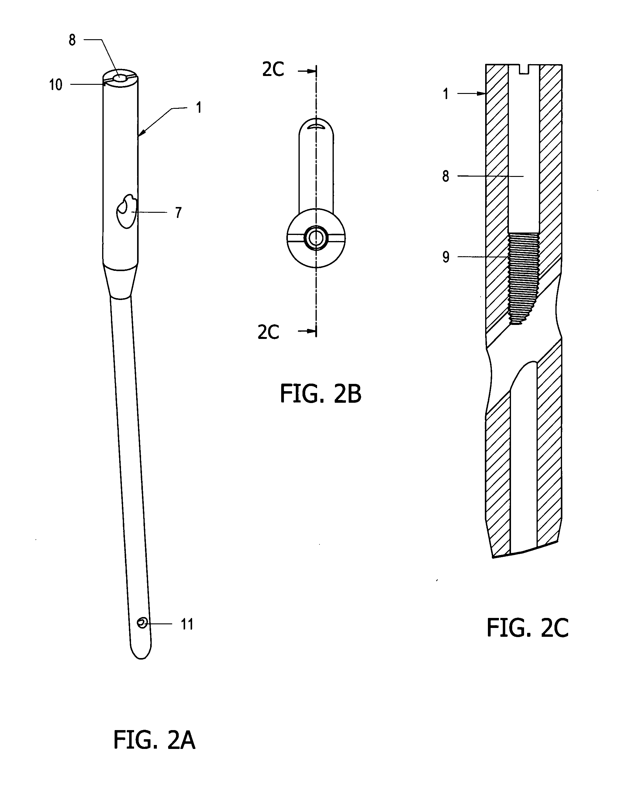
[0044]FIG. 1 illustrates the individual components of the first embodiment of the present invention. In the illustrated embodiment, the device includes an intramedullary nail 1 and two femoral hip implants: the hip screw 3, and the hip peg 4. The optional conventional distal locking screw 2, and an optional coaxial screw 6 are also shown.

[0045]The intramedullary nail 1 is illustrated in FIGS. 2A, 2B and 2C. The intramedullary nail 1 is provided with an oblique opening 7 proximate to its upper end. This oblique opening 7 has a figure eight shape so as to receive the double hip implant assembly 5, and is angled so that when the intramedullary nail 1 is positioned inside the medullary channel, the axis of the oblique opening 7 is directed toward the axis of the femoral neck. The intramedull...

second embodiment

[0051]Next, a device to immobilize bone fragments of fractures occurring in the proximal region of the femur according to the present invention will be explained with reference to FIGS. 9-13A.

[0052]As shown in FIG. 9, the second embodiment of the present invention consists of a side plate 27 with a barrel 31 and two femoral hip implants: the hip screw 28 and the hip peg 29.

[0053]As illustrated in 10A, 10B, and 10C, the side plate 27 consists in a plate with multiple bores 33, which receive the screws that affix the side plate 27 to the femur. At its proximal end, said side plate 27 is solidly affixed to an oblique barrel 31, which has a figure eight shaped cannulation 32. The barrel 31 is angled, so that when the side plate 27 is affixed to the femoral shaft, the axis of the barrel 31 is aligned with the axis of the femoral neck. The figure eight shaped cannulation 32 of the barrel 31 is designed to accommodate the double hip implant assembly, which slidably passes through said figu...


PUM


Abstract

A novel apparatus for treating fractures of the femur is disclosed. The assembly includes two hip implants positioned into the head and neck of the femur. The hip implants solidly lock into each other, while retaining the possibility of being slided together through either the oblique bore of an intramedullary nail or through the barrel of a side plate. This novel apparatus allows the surgeon to achieve sliding rotational control of the femoral head, while avoiding independent rotation of each screw around its own axis. This novel apparatus also avoids independent sliding of each screw.

Description

BACKGROUND OF THE INVENTION[0001]The present invention relates to a device for use in osteosynthesis to repair femoral fractures, and in particular to a device to immobilize bone fragments of fractures occurring in the proximal region of the femur.[0002]A variety of systems have been developed to treat proximal femoral fractures, which are basically based on a hip nail or a lag screw that is inserted from the side of the femur through the neck and into the femoral head, being afterwards fixed either to an intramedullary nail positioned inside the femoral shaft, or to a side plate positioned in the outside of the femoral shaft.[0003]In 1960, the compression hip screw was introduced permitting improved fixation of proximal femoral fractures, allowing the surgeon to compress the bone fragments towards each other. In 1969, Zickel developed the intramedullary rod and cross nail assembly, disclosed in U.S. Pat. No. 3,433,220, consisting on an intramedullary nail located inside the marrow ...

Claims


Application Information

Patent Timeline
IPC IPC(8): A61B17/58
CPCA61B17/744A61B17/746
Inventor FERNANDEZ DELL'OCA, ALBERTO ANGEL
Owner FERNANDEZ DELLOCA ALBERTO ANGEL
Why Eureka
Try Eureka