
Lacrosse Handle

a lacrosse stick and handle technology, applied in the field of handle portion can solve the problems of affecting the accuracy of the lacrosse stick, and the previous wooden handle was heavy and somewhat cumbersome, so as to achieve the effect of increasing the accuracy, strengthening and more durable, and increasing the impact strength

Inactive Publication Date: 2008-10-23
MORROW DAVID K
View PDF35 Cites 3 Cited by
  • Summary
  • Abstract
  • Description
  • Claims
  • Application Information

AI Technical Summary

Benefits of technology

[0008]It is therefore an advantage of the present invention to provide a lacrosse handle that is stronger and more durable than existing lacrosse handles.

Problems solved by technology

Initially, they were susceptible to damage from excess exposure to water.
Further, these prior wooden handles were heavy and somewhat cumbersome.
Additionally, the wooden handles were also susceptible to breakage.
Moreover, because the wood had to be bent to form the single sidewall and the scoop, a significant amount of time was involved in forming or making each of these wooden lacrosse sticks.
Accordingly, if any portion of the head or the handle broke or was damaged, the entire wooden stick needed to be replaced, which was a costly endeavor.
The initial metal handles were relatively heavy, which provided disadvantages from both a playability standpoint as well as from a safety standpoint.
While these aluminum handles were acceptable from a strength standpoint and are still commonly used today, they are susceptible to damage from external forces.
Further, if the external force is great enough, the stick can even break.
However, both the titanium and aluminum handles are still susceptible to damage.
The damage can be in the form of dents or dings which will typically cause the stick to look worn or used.
This is an undesirable feature for many players and can require a player to prematurely replace the handle or render a handle unplayable.

Method used


Image

  • Lacrosse Handle
  • Lacrosse Handle
  • Lacrosse Handle

Examples


Embodiment Construction

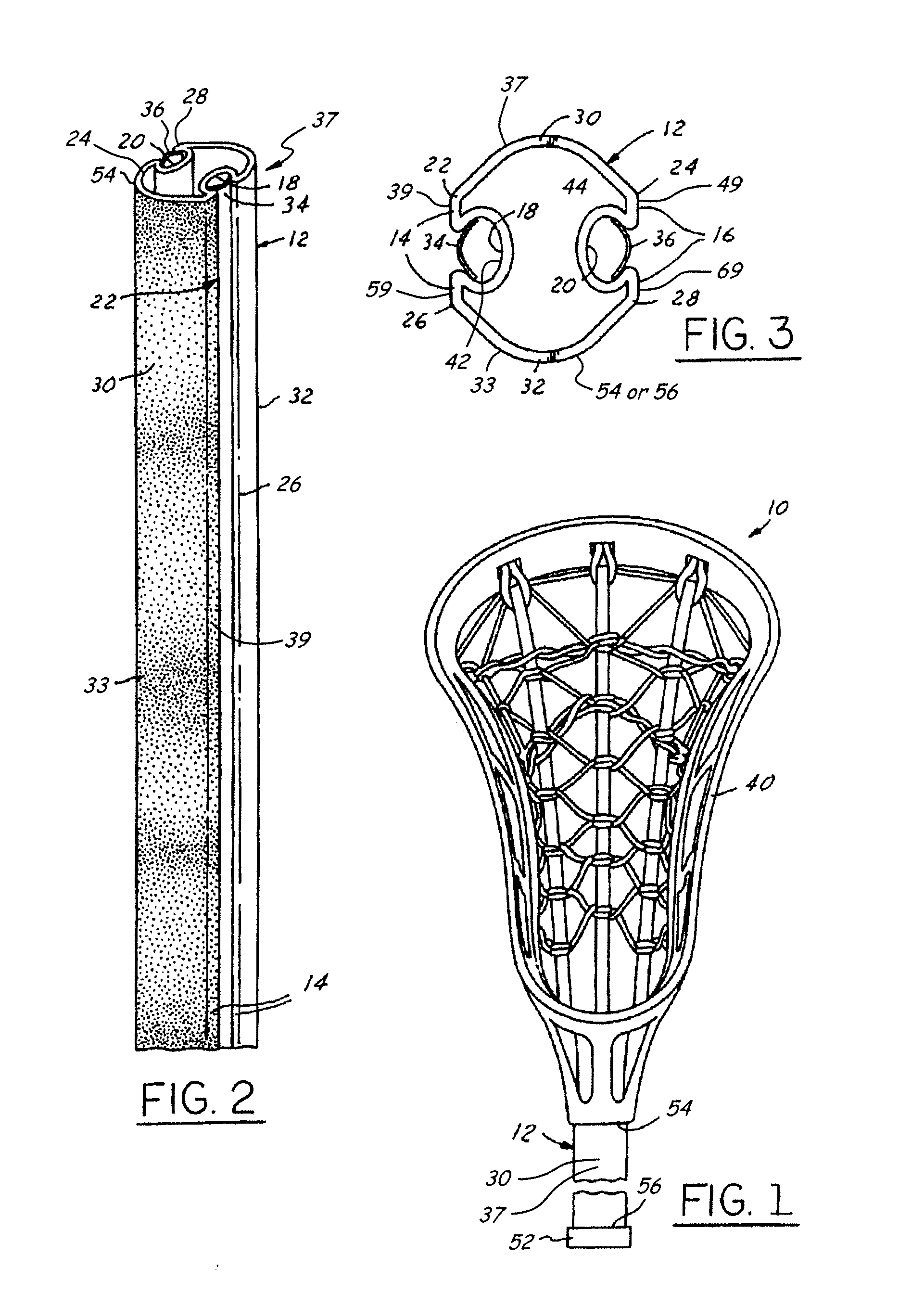
[0025]Referring to FIGS. 1-3, the lacrosse stick of one embodiment of the present invention is generally referred to as reference number 10 and includes an elongated handle 12 that attaches to a lacrosse head 40. In one embodiment, the handle 12 is generally hollow and is constructed of a metallic material, such as aluminum or titanium. It will be understood that the handle 12 can take on a variety of other configurations, i.e. solid or partially solid. Further, the handle 12 can be formed of a variety of other suitable materials, such as graphite, other composite materials, or plastic. The handle 12 has a first side or sidewall 14 and a second side or sidewall 16.

[0026]Each of the sidewalls 14, 16 includes a respective channel 18, 20. Further, each sidewall 14, 16 has a first edge 22, 24 located at an upper edge of the respective channel 18, 20, and a second edge 26, 28 located at a lower edge of the respective channel 18, 20. A first end wall 30 extends between and connects the fi...


PUM

PropertyMeasurementUnit
areaaaaaaaaaaa
surface structureaaaaaaaaaa
impact strengthaaaaaaaaaa

Abstract

A lacrosse handle having two sidewalls each with a channel and two arched walls extending between the sidewalls is disclosed herein. The channels contribute to increased gripping ability by the user and overall increased strength of the handle. Each channel is capable of receiving an insert that includes individualized information, for example, a school name or colors. Further, one of the arched walls may have a textured surface and the other arched wall may have a smooth surface to provide the user with a more accurate handle to head orientation than conventional lacrosse handles. In an alternative embodiment, one or more strategic portions of the exterior surface of an otherwise conventional lacrosse handle include texture that provides increased grippage and provides the user with a more accurate handle to head orientation than conventional lacrosse handles.

Description

CROSS-REFERENCED TO RELATED APPLICATIONS[0001]The present invention is a continuation-in-part application from U.S. patent application Ser. No. 11 / 160,147, filed Jun. 10, 2005 and entitled “Lacrosse Handle”, which claims priority from U.S. Provisional Application Ser. No. 60 / 578,488, filed Jun. 10, 2004, and entitled “Flower Shaped Handle.”TECHNICAL FIELD[0002]The present invention generally relates to the handle portion of a lacrosse stick for use by participants in the sport or game of lacrosse. The present invention, more particularly, relates to a lacrosse handle that has increased impact strength, allows for increased shooting accuracy and allows for a better grip than conventional lacrosse handles.BACKGROUND OF THE INVENTION[0003]Original lacrosse handles were constructed of wood. These wooden handles were shaped such that the lacrosse handle and lacrosse head were a single one-piece wood structure. These one-piece wooden lacrosse handles suffered from a variety of disadvantag...

Claims


Application Information

Patent Timeline
Patent Type & Authority Applications(United States)
IPC IPC(8): A63B59/02B28B11/06
CPCA63B49/06A63B59/0077A63B59/02A63B2209/02A63B60/48A63B60/52A63B59/20A63B60/06A63B60/08A63B60/00
Inventor MORROW, DAVID K.
Owner MORROW DAVID K
Learn More