
Reconfigurable optical add drop multiplexer core device, procedure and system using such device, optical light distributor, and coupling-ratio assigning procedure

a technology of add drop multiplexer and core device, applied in the field of wavelength division multiplexing, can solve problems such as limiting their usefulness, and achieve the effect of maximizing the power level of the optical wavelength

Active Publication Date: 2008-10-23
TELLABS OPERATIONS
View PDF16 Cites 44 Cited by
  • Summary
  • Abstract
  • Description
  • Claims
  • Application Information

AI Technical Summary

Benefits of technology

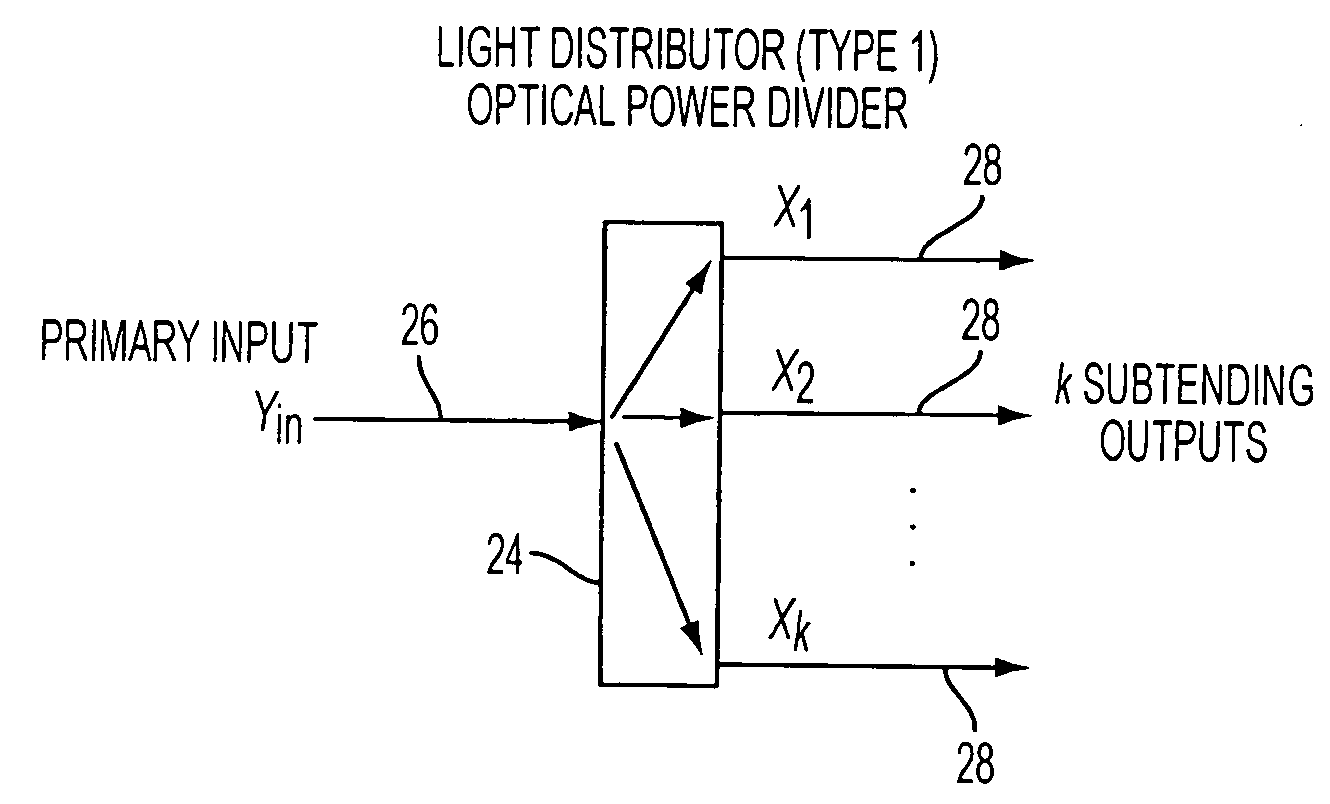
[0014]Further, one or more example embodiments disclosed herein provide a dense wavelength division multiplexing optical add / drop optical node. The node includes first, second, and third sets of optical couplers. The output of the first set of optical couplers and part of the output of the second set of optical couplers is input into the third set of optical couplers. The coupling ratios for the first set of optical couplers is equal among all the inputs of each optical coupler in the first set. The coupling ratios for the second set of optical couplers is such that the power level of an optical wavelength output therefrom along a path directed to a drop port of a first reconfigurable optical add drop multiplexer core device in the node is the minimum required power for optical wavelengths dropped from the first reconfigurable optical add drop multiplexer core device. The coupling ratios for the third set of optical couplers maximizes the power level of the optical wavelength exiting the third set of optical couplers with the lowest optical power.

Problems solved by technology

As a result, while they are reconfigurable, they are not multifunctional, which limits their usefulness.

Method used


Image

  • Reconfigurable optical add drop multiplexer core device, procedure and system using such device, optical light distributor, and coupling-ratio assigning procedure
  • Reconfigurable optical add drop multiplexer core device, procedure and system using such device, optical light distributor, and coupling-ratio assigning procedure
  • Reconfigurable optical add drop multiplexer core device, procedure and system using such device, optical light distributor, and coupling-ratio assigning procedure

Examples


example embodiment # 1

OPTICAL NODE EXAMPLE EMBODIMENT #1

[0100]FIGS. 11 through 14 represent example embodiments of a first optical node. These diagrams illustrate how the FIG. 10(a) ROADM core device can be used in one of three different example modes of operation. The first mode is a two-degree ROADM mode in which each ROADM has k add / drop ports. The second mode is a three-degree ROADM mode. In this mode the add and drop ports comprise a first set of add ports and a first set of drop ports in which the add and drop ports function only as add and drop ports, and a second set of add ports and a second set of drop ports in which the add and drop ports function as both add and drop ports, respectively, and as express ports that are connectable to another ROADM core device. In the second mode, each ROADM has k−1 add ports in the first set and k−1 drop ports in the first set, where k represents the total number of add ports when the add ports in both sets of add ports are combined and k also represents the to...

example embodiment # 2

OPTICAL NODE EXAMPLE EMBODIMENT # 2

[0168]FIG. 18 shows an example embodiment of optical node embodiment #2. More specifically, FIG. 18 shows a four degree node (N=4) 760 including four ROADM core devices 762, 764, 766, and 768. Each of the ROADM core devices shown in FIG. 18 can be the same as, for example, the FIG. 15B ROADM core device, although they are not limited thereto. It is within the scope of the example embodiment for the optical node 760 shown in FIG. 18 to include additional elements and to replace each of the ROADM cores devices shown in FIG. 18 and each of the components of each ROADM core device with any other suitable component (or components) that performs (or perform) the functions thereof. In the node 760, on each ROADM 762, 764, 766, and 768, there are three ports used as express ports, and each ROADM has k−2 add / drop ports that function only as add and drop ports.

[0169]More specifically, the ROADM 762 can comprise a type-4 light distributor 770 receiving optica...

example embodiment # 3

OPTICAL NODE EXAMPLE EMBODIMENT #3

[0238]FIG. 24 shows optical node example embodiment #3 comprising node 1400. This example embodiment can be, but is not limited to being, a simplified view of an example embodiment of an optical node using ROADM example embodiment #3. (For simplicity, the input and output amplifiers are not shown.) More specifically, optical node 1400 can include four ROADM core devices 1402, 1404, 1406, and 1408 that can be the same as, for example, the ROADM core devices shown in FIG. 20d, although they are not limited thereto. It is within the scope of the example embodiment for the optical node 1400 to include additional elements not shown in FIG. 24 and for any of the FIG. 20d ROADM core devices in the node 1400 to be replaced by any other component (or components) that performs (or perform) the functions thereof. It is also within the scope of the example embodiment for any of the expansion ports shown in FIGS. 20a-20d, 21, 22, 23, and 24 to also be added to t...


PUM


Abstract

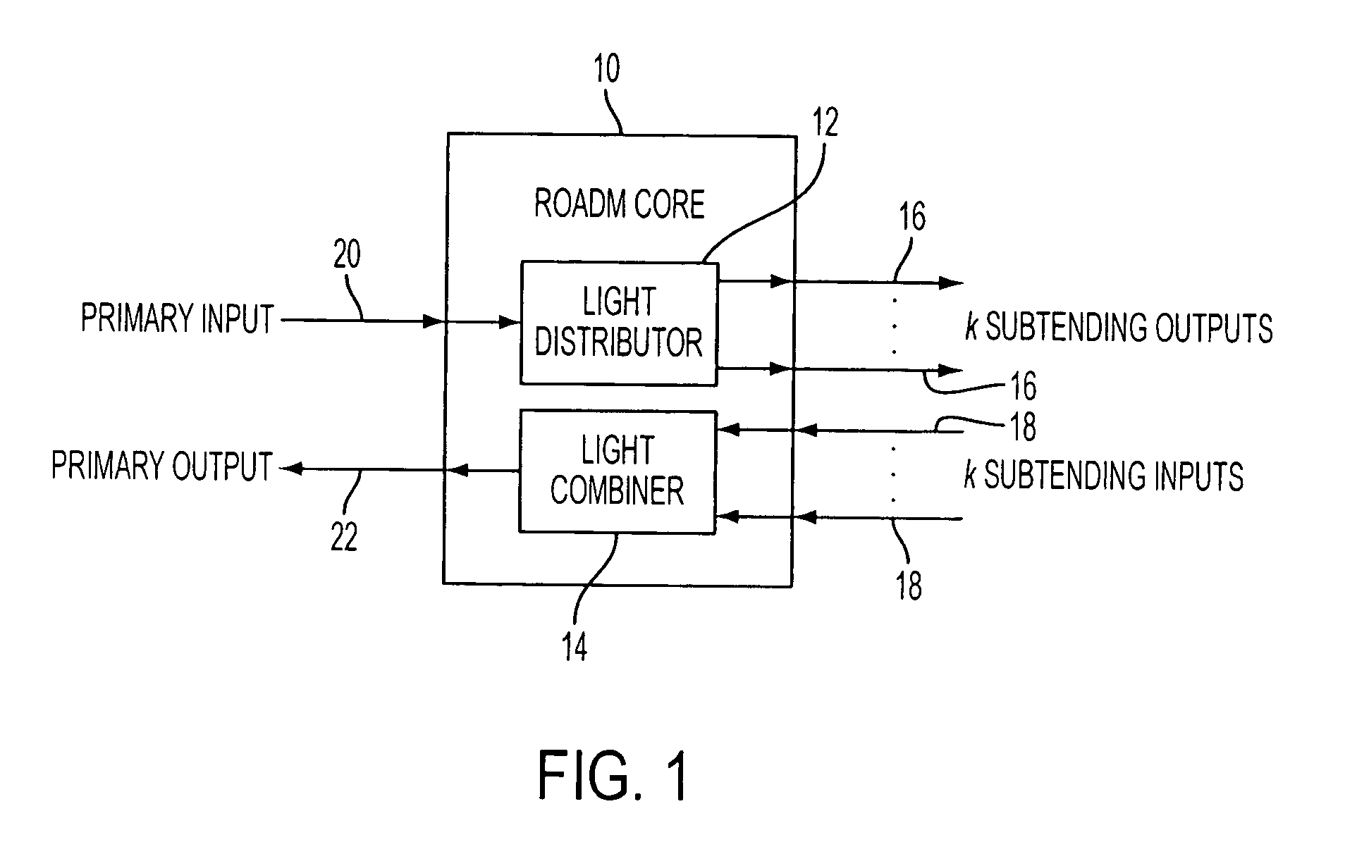
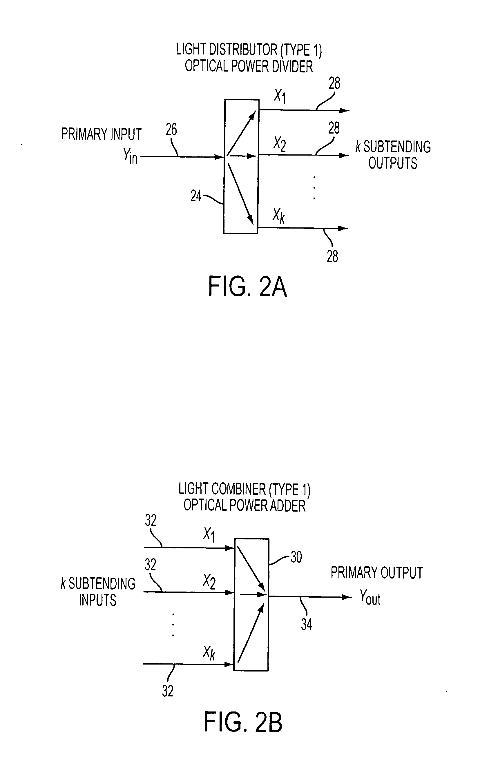
A reconfigurable optical add drop multiplexer core device includes a light distributor, a light combiner, and first and second sets of add and drop ports. The light distributor is configured to receive an optical signal along a primary input of the reconfigurable optical add drop multiplexer core device and to distribute the received optical signal along a plurality of subtending outputs. The light combiner is configured to receive optical signals along a plurality of subtending inputs, to combine the received optical signals into a combined signal, and to output the combined signal. The add and drop ports in the first set function as add and drop ports, respectively, and the add and drop ports in the second set function as both add and drop ports, respectively, and as express ports connectable to another reconfigurable optical add drop multiplexer core device.

Description

CROSS-REFERENCE TO RELATED APPLICATIONS[0001]This application claims the benefit of U.S. Provisional Application No. 60 / 907,565 filed Apr. 9, 2007.INCORPORATION BY REFERENCE[0002]The present application incorporates by reference the contents of the U.S. Provisional Application No. 60 / 907,565 and appendices 1, 2, and 3 thereof in their entirety as if fully set forth herein.BACKGROUND[0003]1. Field[0004]Example embodiments disclosed herein relate in general to the field of wavelength division multiplexing and more particularly to a multifunctional reconfigurable network element, and a DWDM optical node, optical network, and procedure.[0005]2. Related Art[0006]Wavelength Division Multiplexing (WDM) and Dense Wavelength Division Multiplexing (DWDM) are technologies that enable a multitude of optical wavelengths of differing frequencies to be transported over a single optical fiber. A DWDM network is constructed by interconnecting multiple DWDM network elements. Each network element typi...

Claims


Application Information

Patent Timeline
IPC IPC(8): H04J7/00
CPCH04J14/0204H04J14/0205H04J14/0206H04J14/0212H04J14/0213H04J14/0217H04J14/0219H04J14/0221
Inventor BODUCH, MARK E.PAPAKOS, KIMONBUESCHER, GILBERT A.
Owner TELLABS OPERATIONS
Learn More