
Holographically enhanced photovoltaic (HEPV) solar module

Inactive Publication Date: 2008-10-23
MIGNON GEORGE V +1
View PDF6 Cites 33 Cited by
  • Summary
  • Abstract
  • Description
  • Claims
  • Application Information

AI Technical Summary

Problems solved by technology

The luminescent centers reradiate longer wavelength light in a 360 degree solid angle and so are inefficient in directing light to one edge of the plate or to a small region of the edge.
However, this solar concentrator needs to be aligned to the sun and does not provide for any passive solar tracking ability.
However, Ando et al employ a single angle of incidence and a single wavelength, and thus require a tracking mechanism and cannot utilized the entire solar spectrum.
This invention has the disadvantage of multiple reflection losses in the guiding plate and high absorption losses in some of the more cost effective embodiments.
Also this invention posses difficult optical fabrication problems and hence is more expensive to fabricate.

Method used


Image

  • Holographically enhanced photovoltaic (HEPV) solar module
  • Holographically enhanced photovoltaic (HEPV) solar module
  • Holographically enhanced photovoltaic (HEPV) solar module

Examples


Embodiment Construction

[0020]A. Examples of Planar Solar Concentrators

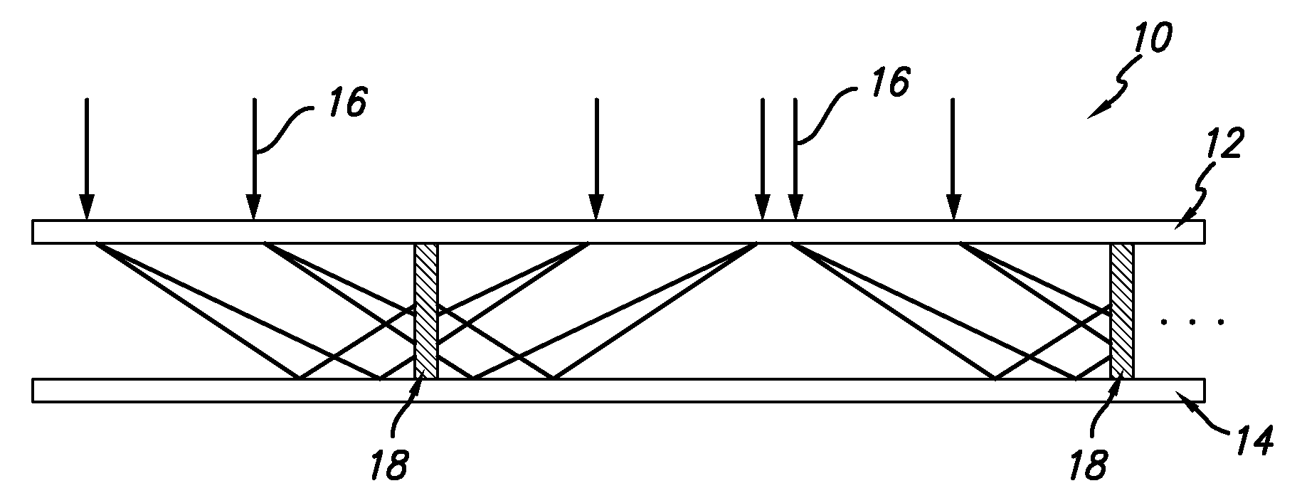
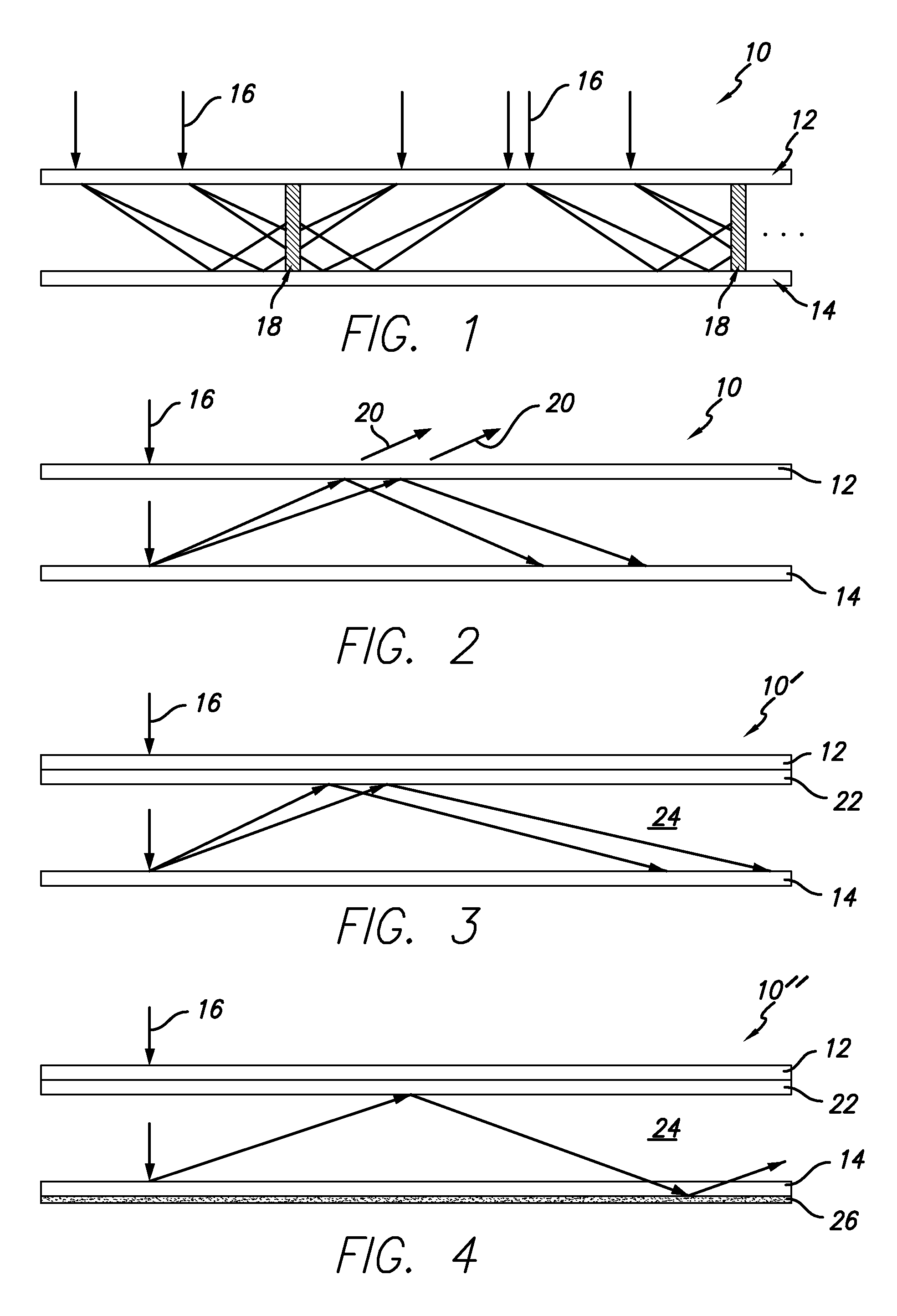
[0021]In this invention, we disclose a planar solar concentrator that is light weight, high efficiency, and low cost. FIG. 1 depicts one embodiment of the planar solar concentrator 10 of the invention. It uses a transmission grating 12 on the top side (the side closer to the sun) and a first reflection grating 14 on the bottom, or opposite, side to concentrate sunlight 16 onto mono-facial or bifacial solar cells 18, as shown in FIG. 1. There is a rigid structure (not shown) to support the gratings and the solar cells.

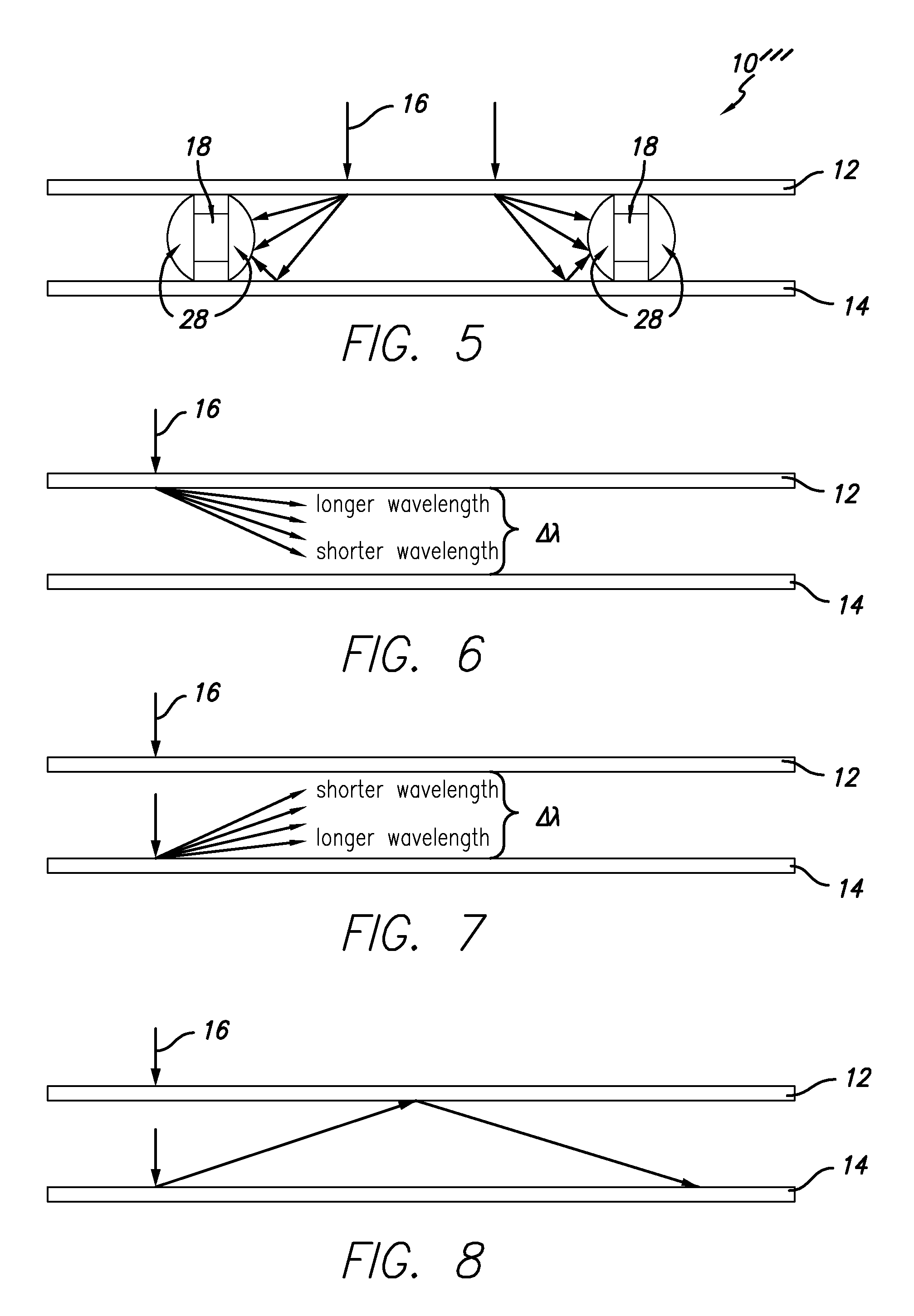
[0022]The holographically enhanced photovoltaic solar module comprises: a first substrate having an outer major surface and an inner major surface, substantially parallel to each other. The first substrate is optically transparent and includes a transmission grating on the inner major surface of the optically transparent substrate. The solar module further includes a second substrate having an outer major surface and an inn...


PUM


Abstract

A holographically enhanced photovoltaic solar module comprises: a first substrate having an outer major surface and an inner major surface, substantially parallel to each other, the first substrate being optically transparent and including a transmission grating on the inner major surface of the optically transparent substrate; a second substrate having an outer major surface and an inner major surface, substantially parallel to each other, the second substrate including a reflection grating on the inner major surface of the second substrate; and at least one solar cell interposed between the transmission grating and the reflection grating and oriented perpendicular thereto.

Description

CROSS-REFERENCE TO RELATED APPLICATION[0001]The present application claims priority from provisional application 60 / 923,869, filed Apr. 17, 2007. Reference is made therein to Disclosure Document 575197, filed on Apr. 18, 2005.BACKGROUND ART[0002]Luminescent solar concentrators are known in the art and act to trap and collect light from luminescent centers dispersed in a planar sheet. Luminescent concentrators utilize the total internal reflection in the wave-guide to trap a portion of the light emitted from the luminescent centers. The luminescent centers reradiate longer wavelength light in a 360 degree solid angle and so are inefficient in directing light to one edge of the plate or to a small region of the edge.[0003]One example of a solar concentrator known in the art utilizes a hologram and a prism or plate; see, e.g., U.S. Pat. No. 4,863,224, issued to Afian et al. However, this solar concentrator needs to be aligned to the sun and does not provide for any passive solar tracki...

Claims


Application Information

Patent Timeline
IPC IPC(8): H01L31/052H01L31/0232H01L31/18F24S23/70
CPCY02E10/52H01L31/0547H01L31/0543H01L31/042
Inventor MIGNON, GEORGE V.HAN, CHIEN WEI
Owner MIGNON GEORGE V
Learn More