Camshaft Assembly

a camshaft and assembly technology, applied in mechanical equipment, valve drives, machines/engines, etc., can solve the problems of camshafts being sensitive to component manufacturing tolerances, drive shafts being unable to lock in bearings, and inner shafts being unable to rotate relative to the outer tubes of camshafts, so as to reduce the tolerance sensitivity of scp camshaft assemblies

Active Publication Date: 2008-10-23
MECHADYNE INT
View PDF6 Cites 25 Cited by
  • Summary
  • Abstract
  • Description
  • Claims
  • Application Information

AI Technical Summary

Benefits of technology

[0005]The present invention seeks therefore to provide a design for reducing the tolerance sensitivity of an SCP camshaft assembly.

Problems solved by technology

This results in the camshafts being sensitive to component manufacturing tolerances.
If significant misalignment is present, the fitting of the connecting member will act to align the holes and this will cause the drive shaft to lock in its bearings in the outer tube of the camshaft.
Variation in components due to manufacturing tolerances can therefore result in the inner shaft being unable to rotate relative to the outer tube of the camshaft.
The need for the component parts of the camshaft to be made to an accurate specification increases the manufacturing cost of the camshaft.

Method used


Image

  • Camshaft Assembly
  • Camshaft Assembly
  • Camshaft Assembly

Examples


Embodiment Construction

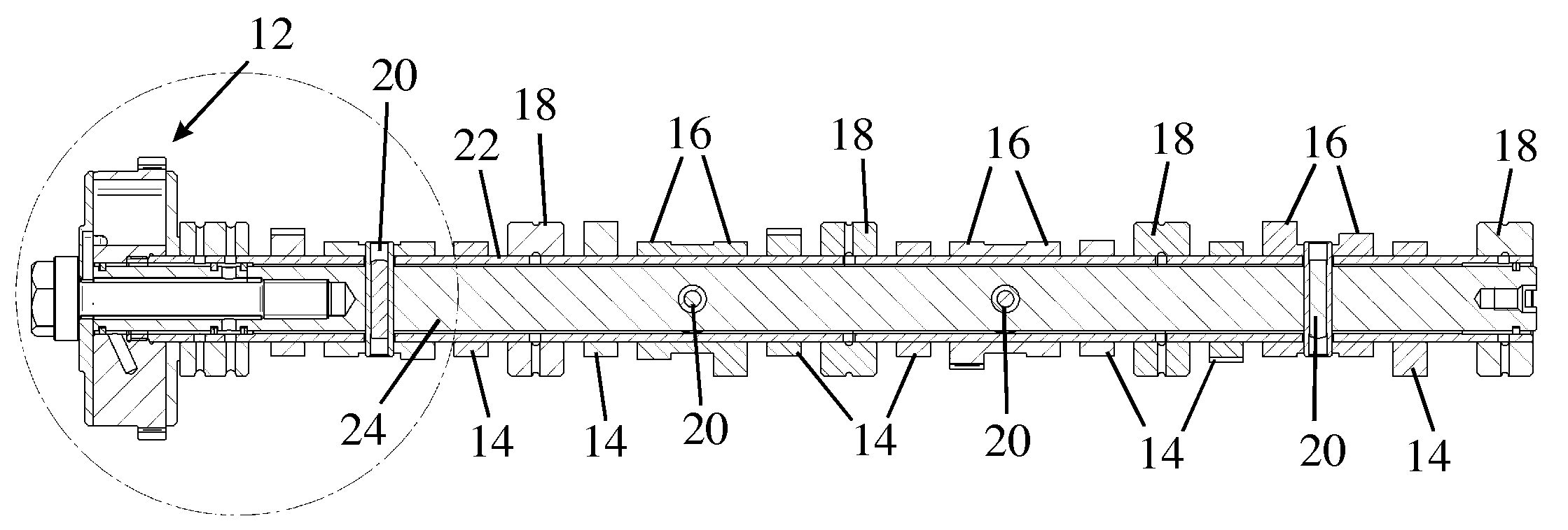
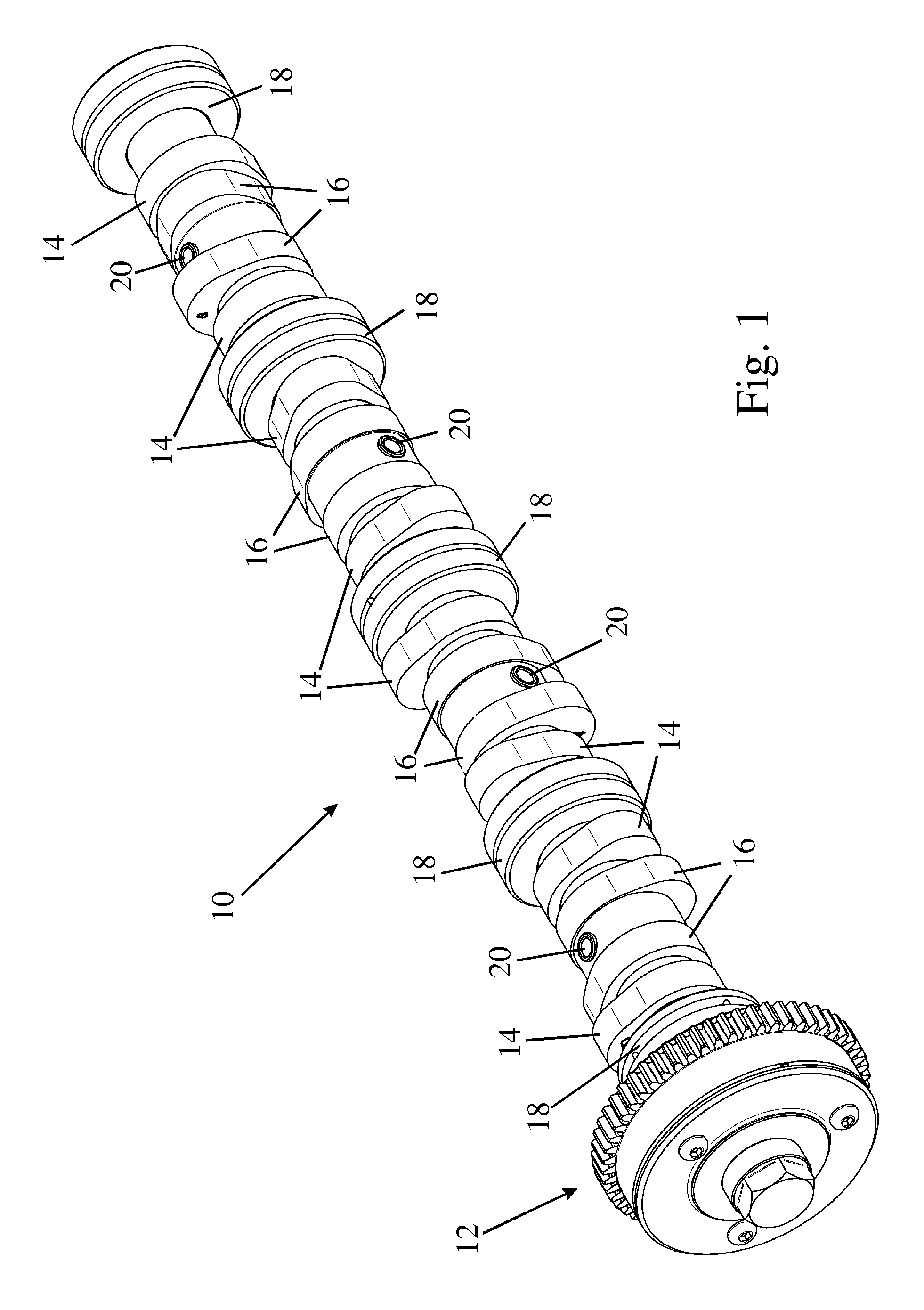
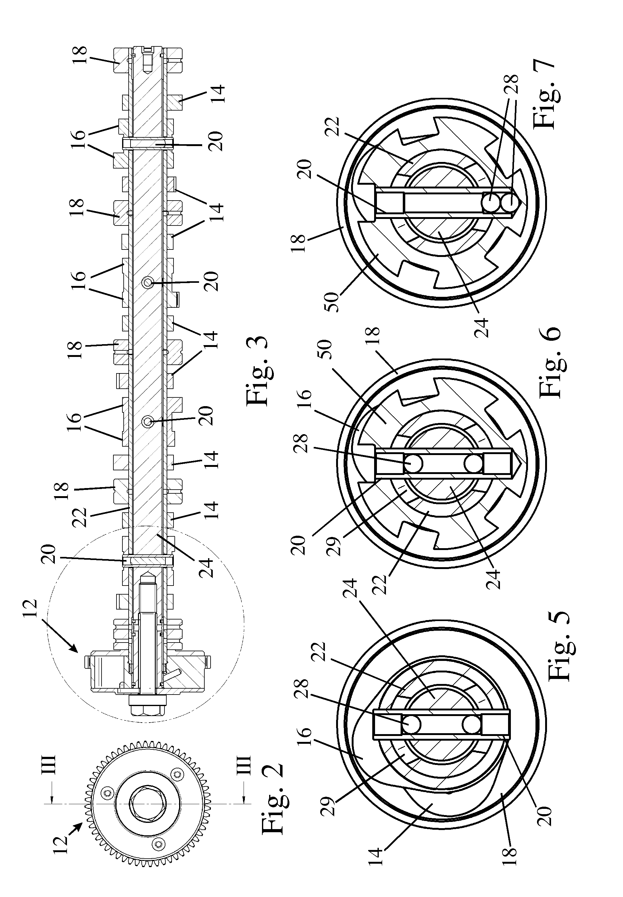
[0021]FIGS. 1 to 4 show an assembled camshaft 10 with a camshaft phaser 12 mounted on one of its ends. The phaser 12 is not described in detail but may for example be a vane type phaser as described in GB 0428063.2. The assembled camshaft 10 comprises an outer tube 22 and an inner shaft 24 arranged within the outer tube 22 but not supported by it nor making direct contact with it. Directly mounted on the outer tube 22 for rotation therewith are cams 14 of a first group and support bearings 18. The bearings 18 and cams 14 may for example be heat shrunk onto the outer tube 22.

[0022]A plurality of sleeves formed with cams 16 of a second group are mounted to rotate freely about the outer surface of the outer tube 22 and are connected by means of pins 20 for rotation with the inner shaft 24. As can be seen from FIGS. 1 and 3, the axes of the two end pins 20 are arranged in a plane perpendicular to that containing the axes of the two remaining intermediate pins 20. Because of the mutual i...


PUM


Abstract

The invention relates to a camshaft assembly comprising an inner shaft, an outer tube rotatable relative to the inner shaft, and two groups of cams mounted on the outer tube, the first group of cams being fast in rotation with the outer tube, and the second group being rotatably mounted on the outer surface of the tube and being connected for rotation with the inner shaft by means of connecting members that pass through circumferentially elongated slots in the outer tube. In the invention, the outer tube surrounds the inner shaft with clearance and the members connecting different ones of the cams of the second group to the inner shaft are inclined relative to one another and act to locate the axis of the inner shaft relative to the outer tube.

Description

FIELD OF THE INVENTION[0001]The present invention relates to a camshaft assembly comprising an inner shaft, a coaxial outer tube rotatable relative to the inner shaft, and two groups of cams mounted on the outer tube, the first group of cams being fast in rotation with the outer tube and the second group of cams being rotatably mounted on the tube and being connected for rotation in phase with the inner shaft by means of connecting members that pass through circumferentially elongated slots in the outer tube. This type of camshaft assembly, herein also termed an “SCP camshaft”, allows the timing of its two groups of cams to be varied in relation to one another by relative rotation of the outer tube and the inner shaft.BACKGROUND OF THE INVENTION[0002]SCP camshafts should not be confused with camshafts of the type described in DE 4419557 where the inner shaft can intentionally be moved radially relative to the outer tube into an eccentric position for the purpose of achieving variabl...

Claims


Application Information

Patent Timeline
Patent Type & Authority Applications(United States)
IPC IPC(8): F01L1/344F01L1/047
CPCF01L1/047Y10T74/2102F01L2001/0473F01L1/34413F01L1/3442
Inventor LANCEFIELD, TIMOTHY MARKMETHLEY, IANOWEN, RICHARD ALWYNLAWRENCE, NICHOLAS JAMES
Owner MECHADYNE INT
Why Eureka
Try Eureka