[0003]The invention is based on a hand-guided sander having a housing whose size is essentially limited to that of the base of the sanding plate. It is preferable for the housing to be equipped to accommodate a rechargeable battery unit. Preferably, the housing has a receptacle to accommodate a rechargeable battery unit with one or more rechargeable batteries. Preferably, the housing contains at least one motor, a sanding drive unit for a sanding plate, the rechargeable battery unit, and an
electronic unit, thus comprising a very compact, easy-to-operate sander. The sander is easier to use thanks to its low center of gravity. The available sanding surface area is large in comparison to the compact housing size. A suitable matching of the components such as the motor, the rechargeable battery unit, and the sanding block makes it possible to achieve high performance at a low weight. It is useful for the rechargeable batteries to be aligned parallel to one another and parallel or slightly inclined in relation to the sanding plate. The motor is preferably a
direct current motor, typically with an
operating voltage of between 7.2 volts and 14.4 volts. Optionally, the sander can also be designed to operate on
power grid current. For the sake of convenience, it is particularly advantageous to operate the sander cordlessly since its operation is then unhindered by a cable that must be managed and the user can work without being troubled. It is also possible to eliminate the weight of the
transformer and cable, which further improves operation and reduces weight.
[0004]For flexible use, the sander should be designed so that it can be operated either cordlessly or on current from the
power grid.
[0005]A particularly compact design with high sanding power can be achieved if
lithium-
ion cells are used as the cells of the rechargeable battery unit. Using a rechargeable battery unit that is equipped with
lithium-
ion cells and has an output
voltage in the neighborhood of 7.2 volts strikes a favorable balance between the arrangement and number of rechargeable cells in the rechargeable battery unit and the power these cells deliver. If a particularly high sanding power in
cordless operation is required, then it is favorable to use a
lithium-
ion cell rechargeable battery unit with an output power of 10.8 volts.
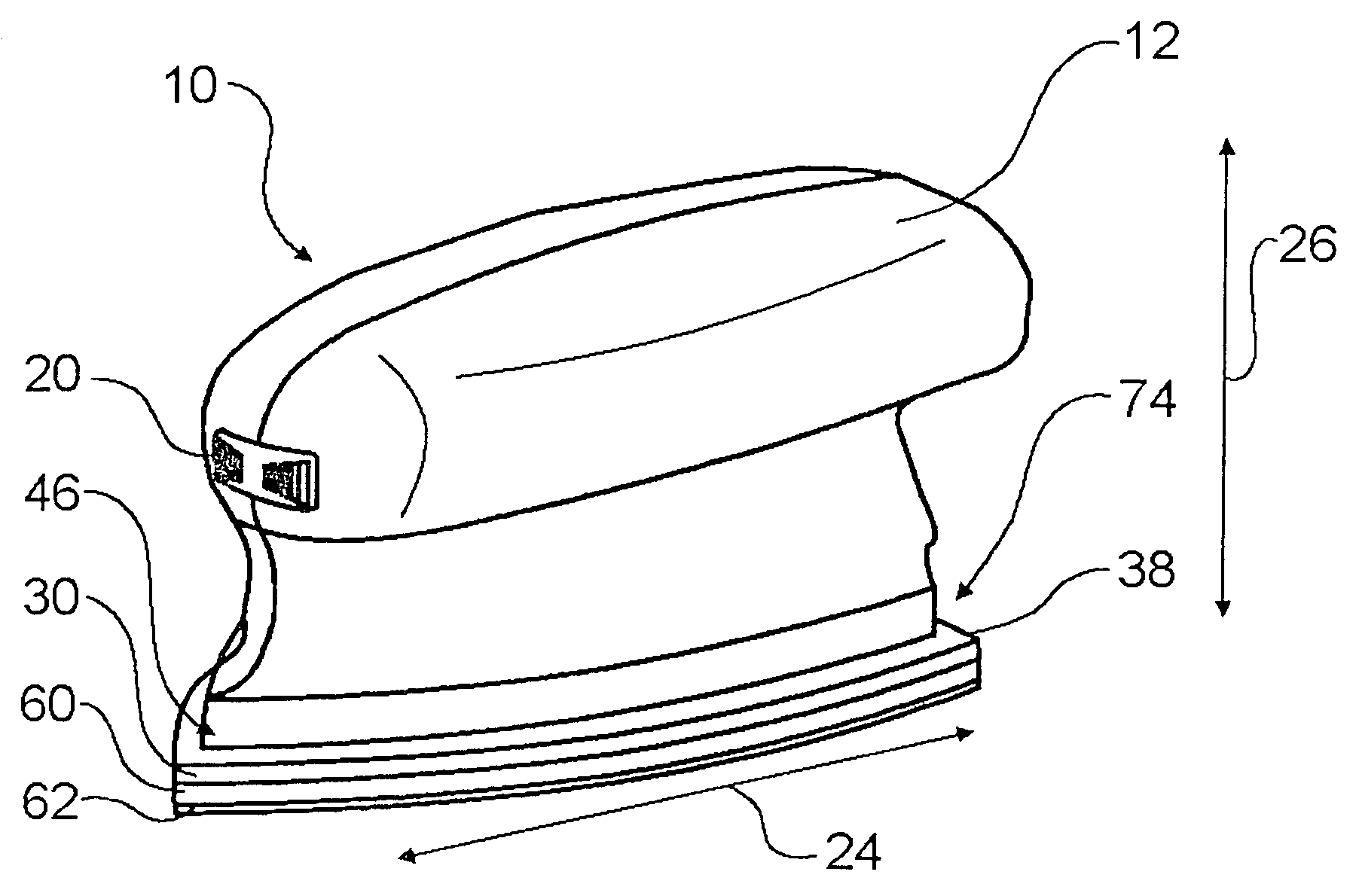
[0006]The sander can be particularly convenient to use if the vertical height of the housing perpendicular to the base is at most as great as its longitudinal span along the base. This situates the center of gravity in an advantageously low position close to the sanding plate. Preferably, the sanding plate has a tip that facilitates access to corners and edges. It is particularly advantageous for the sanding plate to be
delta-shaped or to be comprised of two
delta-shaped surfaces that adjoin each other along their bases.
[0009]In terms of weight, it is also advantageous for a sanding block attached to the sanding plate to be designed to accommodate a sanding disk made of an
elastomer such as rubber or
foam rubber. It is also optionally possible to use
cork. Moreover, with a vertically installed motor, it is possible to provide an inexpensive transmission embodied in the form of a pair of spur gears. The transmission can reduce a bearing load on the sanding plate.
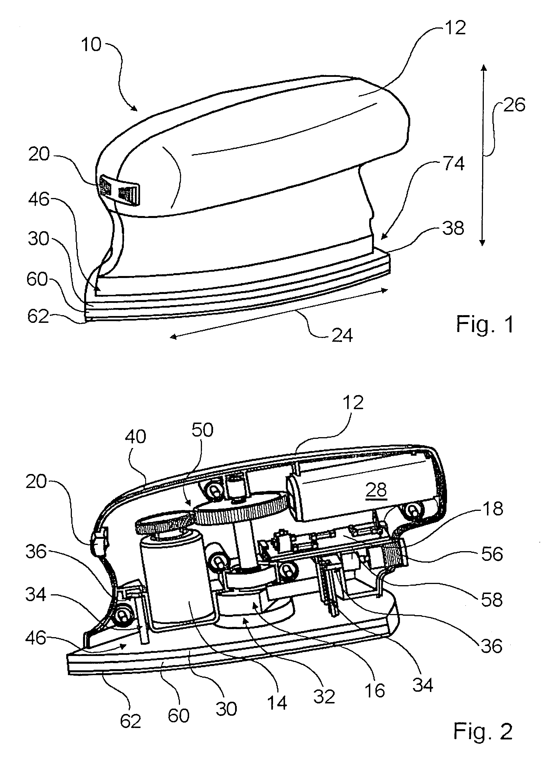
[0008]In a preferred embodiment, a favorable balance among sanding power, convenience, weight, and costs is struck if, in the preferred mid-level operating voltages, the motor is oriented perpendicular to the sanding plate. At an advantageous
operating voltage of approximately seven volts, the height of the motor is relatively low, allowing the motor to be installed into the low housing of the sander in a perpendicular orientation. In the
operating voltage range mentioned above, a favorable sanding power is achieved in the form of a maximum sanding time on a single
battery charge, with an acceptable motor and battery size, which also permits the components to be of a convenient size. A space-saving arrangement with a perpendicularly oriented motor is achieved if an
electronic unit is oriented with a flat side parallel to the sanding plate.
[0009]In terms of weight, it is also advantageous for a sanding block attached to the sanding plate to be designed to accommodate a sanding disk made of an
elastomer such as rubber or
foam rubber. It is also optionally possible to use
cork. Moreover, with a vertically installed motor, it is possible to provide an inexpensive transmission embodied in the form of a pair of spur gears. The transmission can reduce a bearing load on the sanding plate.
[0010]In order on the one hand to permit the motor to be operated in an advantageous efficiency range and on the other hand to permit an oscillation rate of marginally higher than 10,000 / min, the transmission appropriately has a ratio of at most i=3, particularly preferably of i=2. The
motor speed of 20,000 rpm thus achieved lies in a speed range that is suitable for such motors.
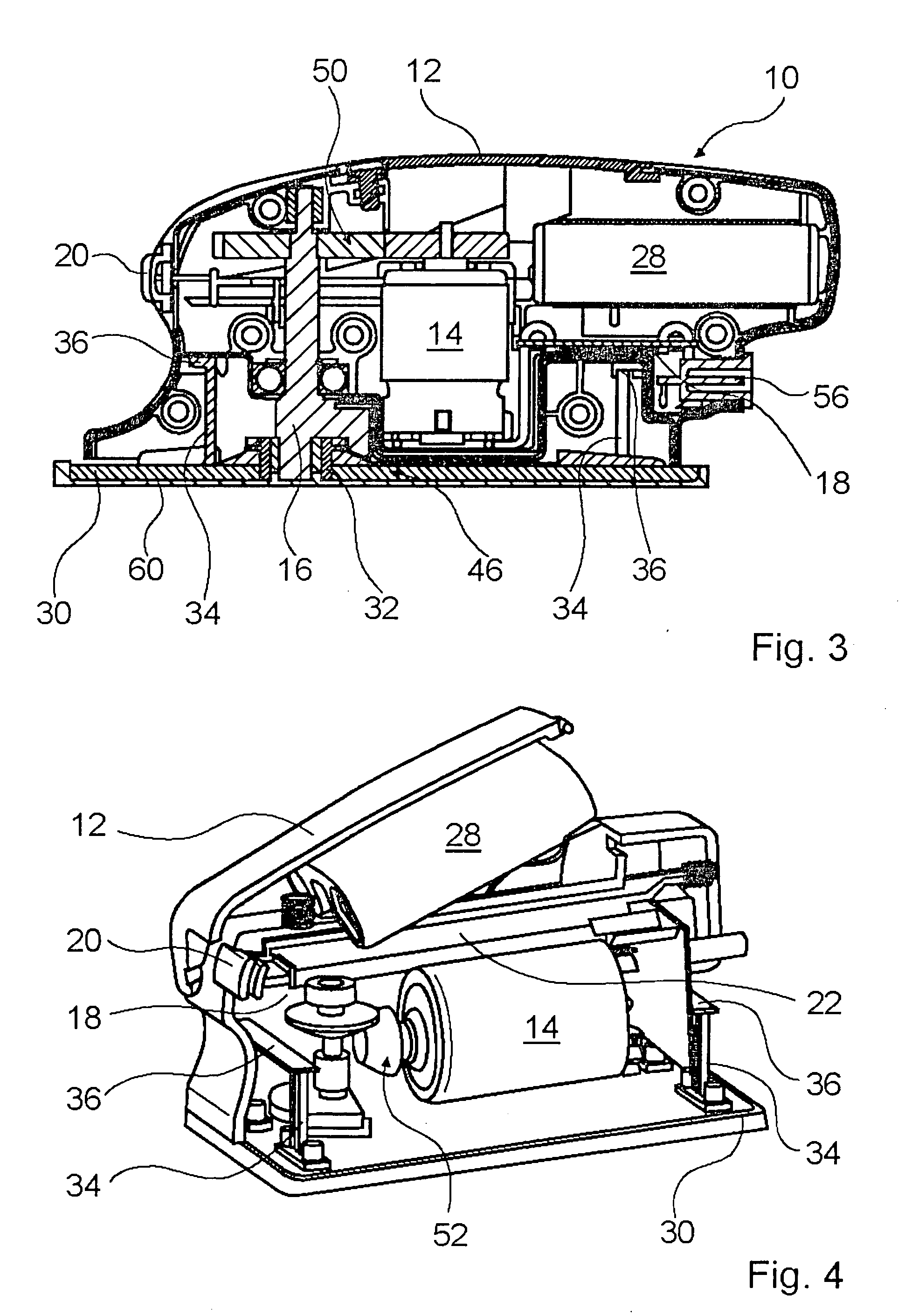
[0011]If a higher sanding power is required, then in another preferred embodiment, it is advantageous to orient a motor parallel to the sanding plate. This makes it possible to use both a larger, more powerful motor and a larger-capacity rechargeable battery unit. Then it is also advantageous to orient an electronic unit with a flat side perpendicular to the sanding plate. Then a transmission between the motor and the sanding drive unit with can be suitably embodied in the form of a pair of bevel gears.
[0014]The present invention also relates to a sander cradle that is provided with a connection for attachment to a charger that can be activated when the sander is inserted into it. The sander can then be stored in the cradle during short pauses in operation and recharged at the same time. The sander can be hung onto the cradle or slid into it for storage purposes, for recharging purposes, and / or for temporarily storing it during pauses while sanding.
[0013]If the
electrical connection is designed to assure that an operating
voltage is supplied in at least one operating mode, then it is possible for the sander to be operated even when the rechargeable battery unit has been drained. In this case, the
electrical connection can either be connected to a charger or connected to a
power cable and in a particularly advantageous design, can include a switching device, which, whenever the
power cable is plugged in, automatically switches the sander into an operating mode in which the sander draws its operating current from the
power grid. It is also conceivable for a
transformer, which is suitable for charging the rechargeable battery unit, to be integrated into the housing so that the rechargeable battery unit automatically recharges whenever the
power cable is attached.
[0014]The present invention also relates to a sander cradle that is provided with a connection for attachment to a charger that can be activated when the sander is inserted into it. The sander can then be stored in the cradle during short pauses in operation and recharged at the same time. The sander can be hung onto the cradle or slid into it for storage purposes, for recharging purposes, and / or for temporarily storing it during pauses while sanding.
[0015]It is advantageous for the sander cradle to be provided with a holder for sanding accessories such as sheets of
sandpaper and the like.
[0016]The present invention also relates to a sander housing for containing at least one motor, a sanding drive unit for a sanding plate, and an electronic unit, and having a base to be attached to a sanding plate, whose longitudinal span is at least as great as a height of the housing perpendicular to the base and has a receptacle for a rechargeable battery unit. This achieves a compact, easy-to-use, attractive housing, particularly when the rechargeable battery unit has lithium-ion cells.
[0017]In one advantageous embodiment, the sander housing is divided into a first and second half of the housing casing in which means are provided for holding a motor and / or an electronic unit and / or the rechargeable battery unit and / or a transmission and / or a sanding drive unit for a sanding plate, which are inserted into one or both of the casing halves of the housing. This simplifies
assembly of the sander. Preferably, a dust seal is provided between the electrical and
mechanical components in the sander housing.
