
Automated system and method for blood components separation and processing

a technology of automatic system and blood, applied in the direction of suction device, centrifuge, medical device, etc., can solve the problems of contaminating the plasma with rbc or wbc, affecting the quality of the plasma, and the current technique is labor-intensive, so as to facilitate the installation and dismount the set, and the effect of convenient hand loading

Active Publication Date: 2008-10-09
CHAMMAS JACQUES
View PDF43 Cites 11 Cited by
  • Summary
  • Abstract
  • Description
  • Claims
  • Application Information

AI Technical Summary

Benefits of technology

[0018]The invention provides an automated method and system for simultaneously separating multiple blood units into their components. The automated process reduces cost by eliminating laborious laboratory steps that are inherent in the current separation methods. The automated process improves the quality of the product by minimizing human factors and maintaining process consistency and efficiency. Product quality and purity are enormously enhanced by segregating blood components while the centrifuge is spinning and preserving the separation edge between the different layers. Blood components, red blood cell (RBC), plasma, Platelets, and Leukocytes known as white blood cell (WBC) are segregated in separate bags.
[0020]Segregating the leukocytes from the other components has many benefits in the modern medicine. Most importantly, the reduction of the WBC count in the RBC, Plasma, and platelets improve their medical quality. Also segregated WBC layer helps in isolating stem cells that are widely used for biotech therapeutic applications. Companies are currently isolating stem cells from umbilical cord blood to be stored at very low temperature for future use.
[0021]The disposable set of containers disclosed in this application typically comprises a primary bag interconnected for fluid flow to four satellite bags. One satellite bag contains a therapeutic solution and / or preservative solution. All bags are preferably comprised of flexible plastic films. The primary bag and at least one satellite (plasma) bag has a main chamber having a coned shaped top end with tapered sides connected to a small atrium, i.e. a small defined portion of the volume of the bag that is disposed immediately in communication with the exit of the bag / container having the shape of a convergent funnel leading to the exit port or aperture at the top end of the bag. The geometry of the exit end (the proximal end) of the bag / container is most preferably configured as a cone-like shaped portion that merges into a narrower atrium portion. This geometry at the exit end of the bag / container helps in evenly streamlining the exiting fluid flow through the exit port while the centrifuge is still spinning and assists in preserving the separation edge between the exiting fluid and the remaining fluid as it converges in its flow through the exit port of the bag / container. Tubes interconnecting primary and satellite bags are typically equipped with at least two manifolds containing flow intersection points. These manifolds further assist in mounting the disposable set of containers within the centrifuge apparatus in stable and correct positioning, interconnection and engagement, particularly with respect to flow control valves and sensors. Most preferably, a connecting tube is provided that interconnects the primary bag and a phlebotomy needle that is used to deliver blood from a donor and collect it in the primary bag.
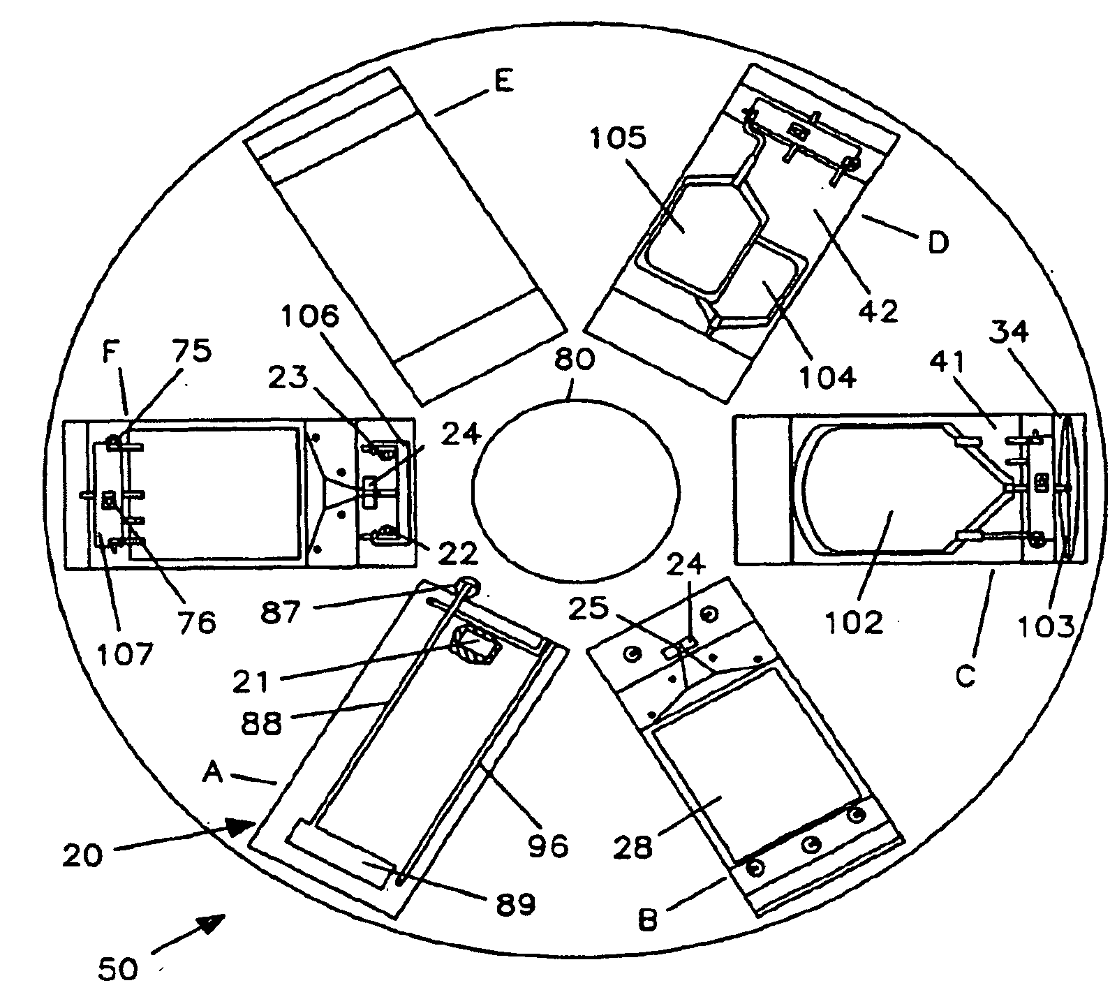
[0026]The disposable set of bags is most preferably installed in a chuck before the set of processing / collecting bags are mounted to the centrifuge rotor. A “chuck” according to the invention is a portable component readily mountable in and dismountable from the centrifuge to facilitate installation of the set of blood processing / collection bags or containers. The chuck is preferably lightweight and readily loadable by hand with a set of bags / containers. The primary bag or container that contains the original whole blood fluid to be separated into its components is typically inserted in a support pouch. The two or more fluid flow manifolds are snap fitted into their appropriate locations and the satellite bags are disposed in their apposite chambers inside the chuck. A chuck carrying loaded with a set of bags / containers is docked in the cradle of the centrifuge. The cradle as shown in the accompanying figures typically has the shape of a rectangular box configured to receive a chuck that is configured to a complementary shape. As shown herein, each cradle has two sets of pneumatic valves located at the two radial extremities of the cradle and are prepared to be engaged with the manifolds from the blood processing set. An optic sensor that detects fluid characteristics such as density is located at the front end of the cradle near the rotating axis. A deformable pressure pad that inflates by pressurized air is disposed between the two valve sets. When the chuck is coupled to / mounted in the cradle, the primary blood bag / container that is inserted in the support pouch and a pressure pad provided for squeezing the bag are confined within a fixed space. The volume of the expandable pressure exerting pad increases only when the volume of the primary blood bag decreases.
[0067]a chuck for securely mounting a plurality of interconnected blood containers to the rotor, the chuck being readily mountable to and dismountable from the rotor,

Problems solved by technology

The difficulty in this step is not to disturb the separation edge between the two layers.
This current technique is labor intensive where human factor has imperative effect on product quality and purity.
Contamination (unwanted RBC or WBC mixed with plasma or platelets) is a known threat to product quality.
Another source of contamination of the PRP is the tendency of the bags contents to swirl during rotor deceleration in an effort to preserve its angular momentum causing RBC and WBC to be mixed with plasma.
Furthermore the handling of the blood bag after centrifugation and the way it is placed it in the extractor may cause contamination of the plasma by RBC or WBC.
Nevertheless, the whole process remains laborious and requires the transfer of separated components from the primary bag to a satellite bag, to be completed quickly with manual intervention before disintegration of the separation edge in order to maintain product purity.
This time limit requires all blood processing procedures to be conducted efficiently and effectively in an environment heavily dependent on human factor and manual operations.

Method used


Image

  • Automated system and method for blood components separation and processing
  • Automated system and method for blood components separation and processing
  • Automated system and method for blood components separation and processing

Examples


Embodiment Construction

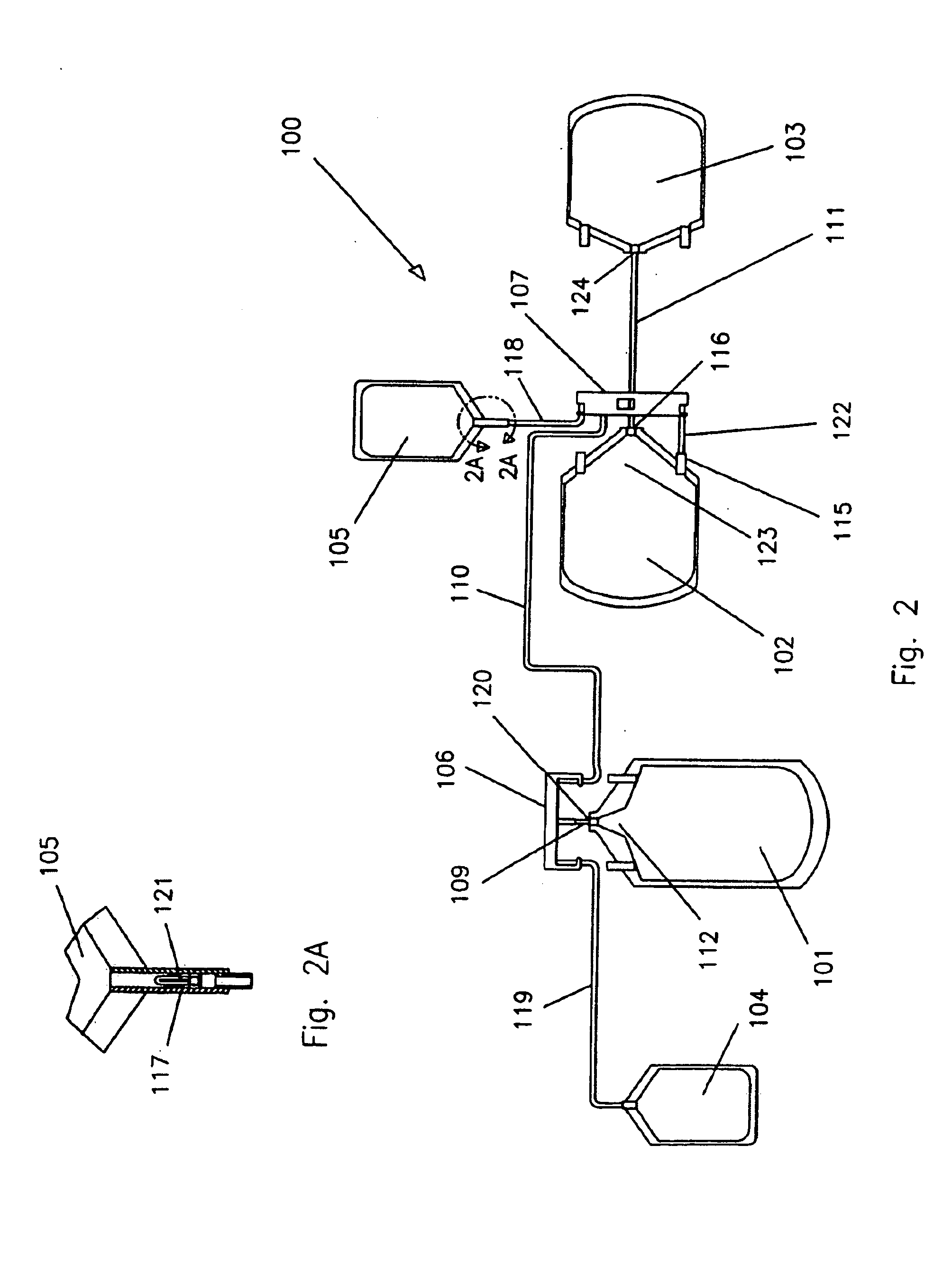
[0105]Referring to FIG. 2, a disposable set of blood processing bags or containers 100 is used to collect blood from a normal donor using standard blood collection method. A phlebotomy needle (not shown in FIG. 2) is inserted in the donor's vein and blood is allowed to flow from the needle through a tube connected to the primary bag 101. When desired amount of blood is collected in the primary bag, the tubing connected to the needle is heat sealed and disconnected from the set.

[0106]FIG. 17 shows a schematic view of a syringe blood processing disposable set. The blood processing set 100 is comprised of a primary bag that is interconnected to multiple satellite bags. All primary and satellite bags are preferably made of flexible plastic material. In FIG. 2, the primary bag 101 is connected to RBC manifold 106. The RBC manifold 106 is preferably made of rigid plastic. It has one inlet that receives the flow exiting the primary bag 101 through tubing 109, and two outlets. One outlet di...


PUM


Abstract

A blood processing centrifuge comprising: a rotor having an axis of rotation and being controllably spun around the axis, a mechanism for processing whole blood within the rotor while spinning, a computer controlling blood processing operations, the computer being mounted to the rotor and spinning therewith.

Description

FIELD OF THE INVENTION[0001]The present invention relates to apparati and methods for processing of blood and more particularly to automated systems and methods for separating components of blood into discrete fractions.BACKGROUND OF THE INVENTION[0002]Transfusion therapy in the past was largely dependent on the use of whole blood. While whole blood may still be used in certain limited circumstances, modern transfusion therapy depends largely on the use of clinically needed blood component. Whole blood consists of many components, primarily, red blood cells, white blood cells, platelets, and plasma. Therefore, a whole blood unit that is collected from a normal donor can be processed to separate it into its components. Each component can then be transfused to a needy individual.[0003]Centrifugation is a known technique for separating blood into its individual components. This is possible because each blood component has its own density. Therefore when whole blood is subjected to high...

Claims


Application Information

Patent Timeline
Patent Type & Authority Applications(United States)
IPC IPC(8): B04B15/00
CPCA61M1/3693A61M2205/331A61M2205/3569A61M1/3698B04B13/00B04B9/14B04B2009/143B04B5/0428A61M1/0209
Inventor CHAMMAS, JACQUES
Owner CHAMMAS JACQUES
Learn More