
Linear Fiber Array Mount To a Spectrometer

Inactive Publication Date: 2008-10-09
LAMBDA SOLUTIONS
View PDF1 Cites 18 Cited by
  • Summary
  • Abstract
  • Description
  • Claims
  • Application Information

AI Technical Summary

Benefits of technology

[0010]The present invention satisfies the above-mentioned need by providing a simple and ease-of-use fiber slit mount for efficiently coupling the linear fiber array to the entrance slit of a spectrometer and also providing a mount for a slitless spectrometer that reduces light loss.
[0012]The mount of the present invention provides a simpler mechanism for coupling of the linear fiber array to the spectrometer entrance slit. It ensures the alignment of the fiber slit to the spectrometer entrance slit, minimizes the light loss due to misalignment of the fiber-slit interface of the conventional design, and thus enhanced the system sensitivity and signal to noise ratio. It eliminates the tedious and difficult manual alignment procedure which is necessary in the conventional design whenever the spectrometer is transported. Furthermore, it is also more stable and secure compared to the conventional mounting mechanism. These advantages permit wide field or clinical uses of advanced analytical instruments, such as Raman spectrometer and fluorescence spectrometer.
[0013]The mount for the linear fiber array of the present invention provides efficient light coupling of the fiber array for the slitless spectrometer. The entrance slit of the spectrometer is removed and the linear fiber array with appropriate core diameter and numerical aperture (NA) is acting as the entrance slit. The core diameter is determined by the spectrometer resolution. The NA should closely match the acceptance angle of the spectrometer optics to achieve high throughput and in the meantime to reduce stray light.
[0015]Since there is not a slit in the spectrometer which may block the light from the fiber, all the light exiting from the fiber enters the spectrometer and no light loss occurs. The light throughput is improved compared to the conventional spectrometer with a slit, so better sensitivity and thus signal-to-noise ratio are achieved. In addition, there is no additional interface between the sample and spectrometer, light loss from a sample is minimized, which results in higher sensitivity. Furthermore, it has other advantages such as reproducible (achieved by the open slot in the adapter and the lock key in the connector) without tedious and difficult manual alignment procedure, stable and ease of use.

Problems solved by technology

This manual alignment procedure is tedious and difficult and requires skilled personnel.
In addition, the mounting mechanism is not stable at all with a single set screw.
Thus it limits its field use.
Particularly it requires tedious realignment after each movement.
With this conventional mounting mechanism, light loss occurs at the fiber optic array and entrance slit interface.
This greatly reduces the system throughput, sensitivity and thus signal-to-noise ratio.
This presents a problem for situations like weak signal to begin with.
Therefore in Raman spectroscopy it cannot afford losing any part of the signal.
There exists light loss due to fiber-fiber coupling at the connector interface.
Therefore the care must be taken to handle it which is inconvenient to the users for routine analysis.

Method used


Image

  • Linear Fiber Array Mount To a Spectrometer
  • Linear Fiber Array Mount To a Spectrometer
  • Linear Fiber Array Mount To a Spectrometer

Examples


Embodiment Construction

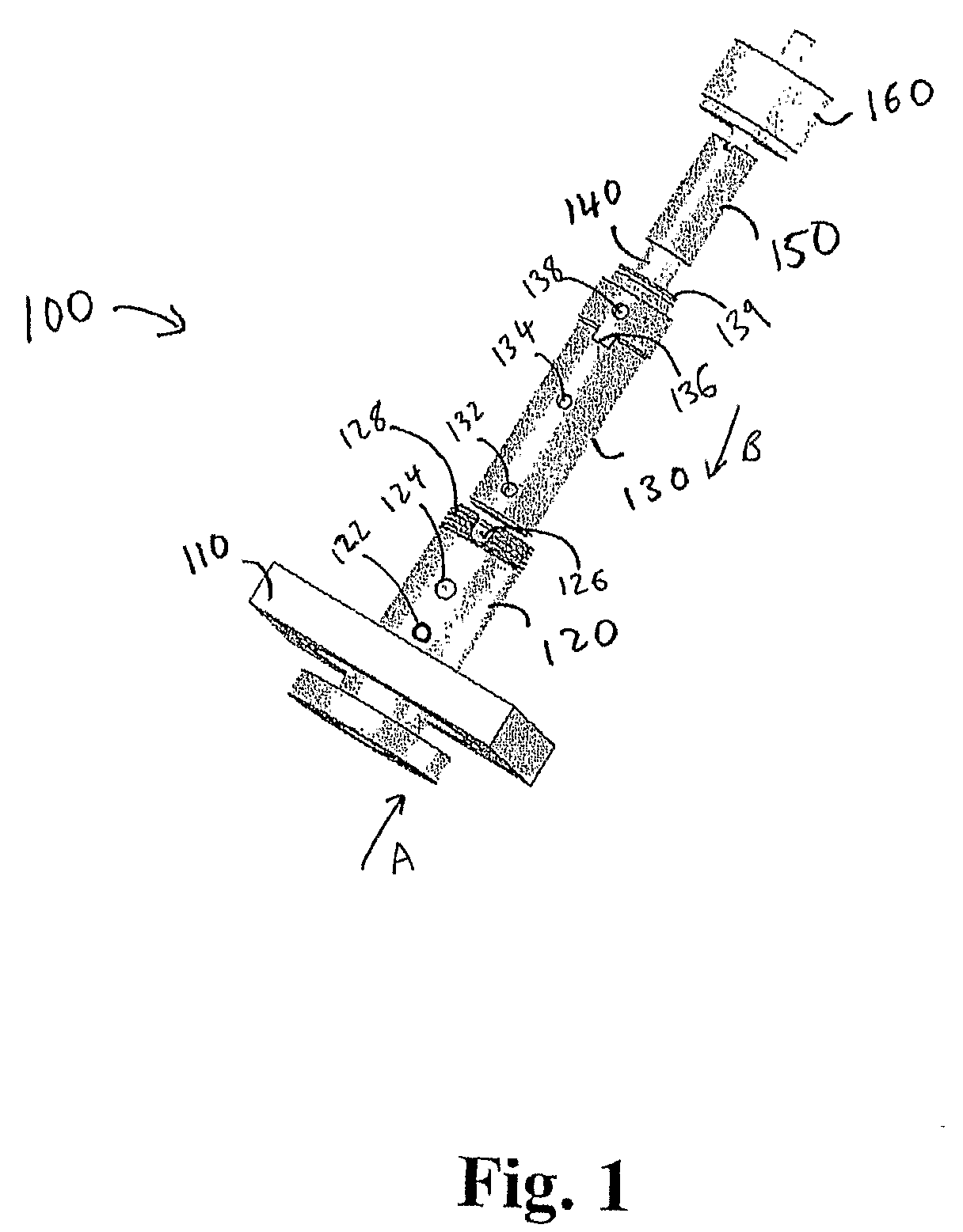
[0030]The present invention provides efficient and ease-of-use fiber bundle coupler to the entrance slit of a spectrometer when light waveguide is used to transfer the light from a sample under investigation. The performance of spectrometer system is improved by the precision machined directional opening in the adapter and the lock key in the connector. The slot in the fiber bundle boot facilitates the adjustment of the fiber bundle to align the linear fiber array along the entrance slit.

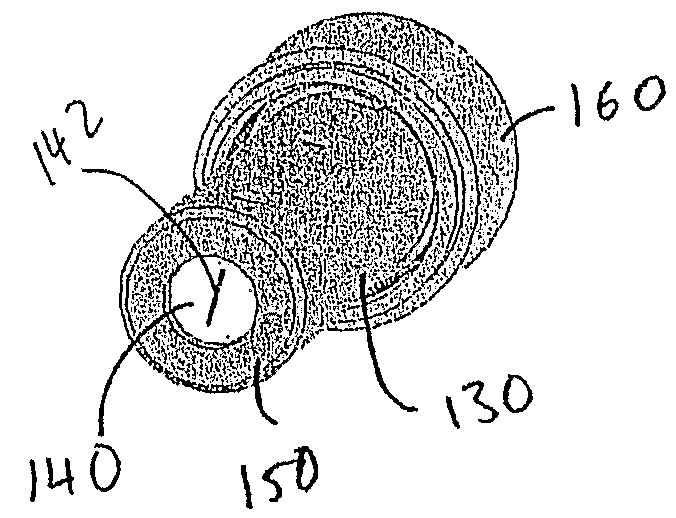
[0031]FIG. 1 shows an exploded view of the linear fiber array mount 100 including all the components, including a mounting plate 110, a directional adapter 120, a lock tube 130 of the connector, a fiber bundle array 140, a fiber bundle boot 150 and a cap 160. The directional adapter 120 comprises holes 122, 124, external threads 128, and a slot 126. The lock tube 130 comprises holes 132, 134, notch 136, a hole 138 and a groove 139 for a cap retaining ring.

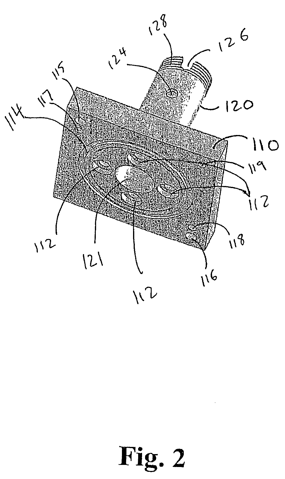
[0032]FIG. 2 shows a directional adapter blo...


PUM


Abstract

A coupler for coupling a linear fiber array to a spectrometer is provided, the coupler having a tube, a linear fiber bundle array inserted through the tube, an alignment mechanism for aligning the linear fiber bundle array with a slit on the spectrometer, and a locking mechanism for locking the linear fiber bundle array to the tube. Further, a method for coupling a linear fiber array to a spectrometer is provided, the method having the steps of inserting a linear fiber bundle array through a tube, aligning the linear fiber bundle array with a slit on the spectrometer, and locking the linear fiber bundle array to the tube once it is aligned with the slit on the spectrometer.

Description

BACKGROUND OF THE INVENTION[0001]1. Field of the Invention[0002]The present invention is related to a mount for coupling a linear fiber array to a spectrometer slit.[0003]2. Prior Art[0004]A spectrometer is an optical instrument used to measure properties of light over a specific portion of the electromagnetic spectrum. The variable measured is most often the light's intensity but could also, for instance, be the polarization state. The independent variable is usually the wavelength of the light, normally expressed as some fraction of a meter, but sometimes expressed as some unit directly proportional to the photon energy, such as wavenumber or electron volts, which has a reciprocal relationship to wavelength. A spectrometer is used in spectroscopy for producing spectral lines and measuring their wavelengths and intensities.[0005]A typical spectrometer includes an entrance slit, a collimating mirror or lens, a wavelength dispersive element, such as grating or prism, a mirror or lens...

Claims


Application Information

Patent Timeline
IPC IPC(8): G01J3/28
CPCG01J3/02G01J3/0218G01J3/0289G01J3/0291G02B6/3885G02B6/4226G02B6/4292
Inventor YANG, YONGWU
Owner LAMBDA SOLUTIONS
Learn More