
Endoscope Relay Lens

a relay lens and endoscope technology, applied in the field of endoscope relay lenses, can solve the problems of not being able unable to correct the curvature of field aberration, and the negative power element is of the well known gauss type, etc., to achieve the effect of simple lenses, low cost and easy calculation

Active Publication Date: 2008-10-02
OLYMPUS WINTER & IBE
View PDF8 Cites 6 Cited by
  • Summary
  • Abstract
  • Description
  • Claims
  • Application Information

AI Technical Summary

Benefits of technology

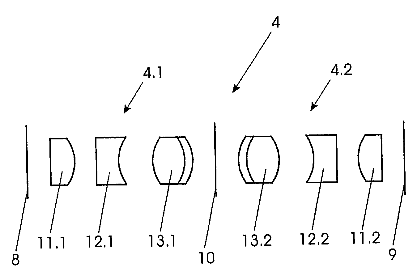
The present invention provides a cost-effective solution for designing relay sets with curvature of field correction. The invention uses a well-known lens design called the Triplet, which is easy to calculate, manufacture, and overcompensates for curvature of field aberration. The relay sets are designed with a strong outer and middle lens units cemented together, and the inner lens is a cemented doublet, which provides more parameters to control aberrations. This design allows for a longer optical system and the addition of additional relay sets with curvature of field correction.

Problems solved by technology

But it is especially difficult to correct for curvature of field aberrations.
The disadvantage of this design is that it cannot correct the curvature of field aberration.
The disadvantage of the system of U.S. Pat. No. 4,676,606 is that the negative power element is of the well known Gauss type.
This optical design is highly complex and extremely expensive and therefore not suited for mass produced endoscopes.

Method used


Image

  • Endoscope Relay Lens
  • Endoscope Relay Lens

Examples


Embodiment Construction

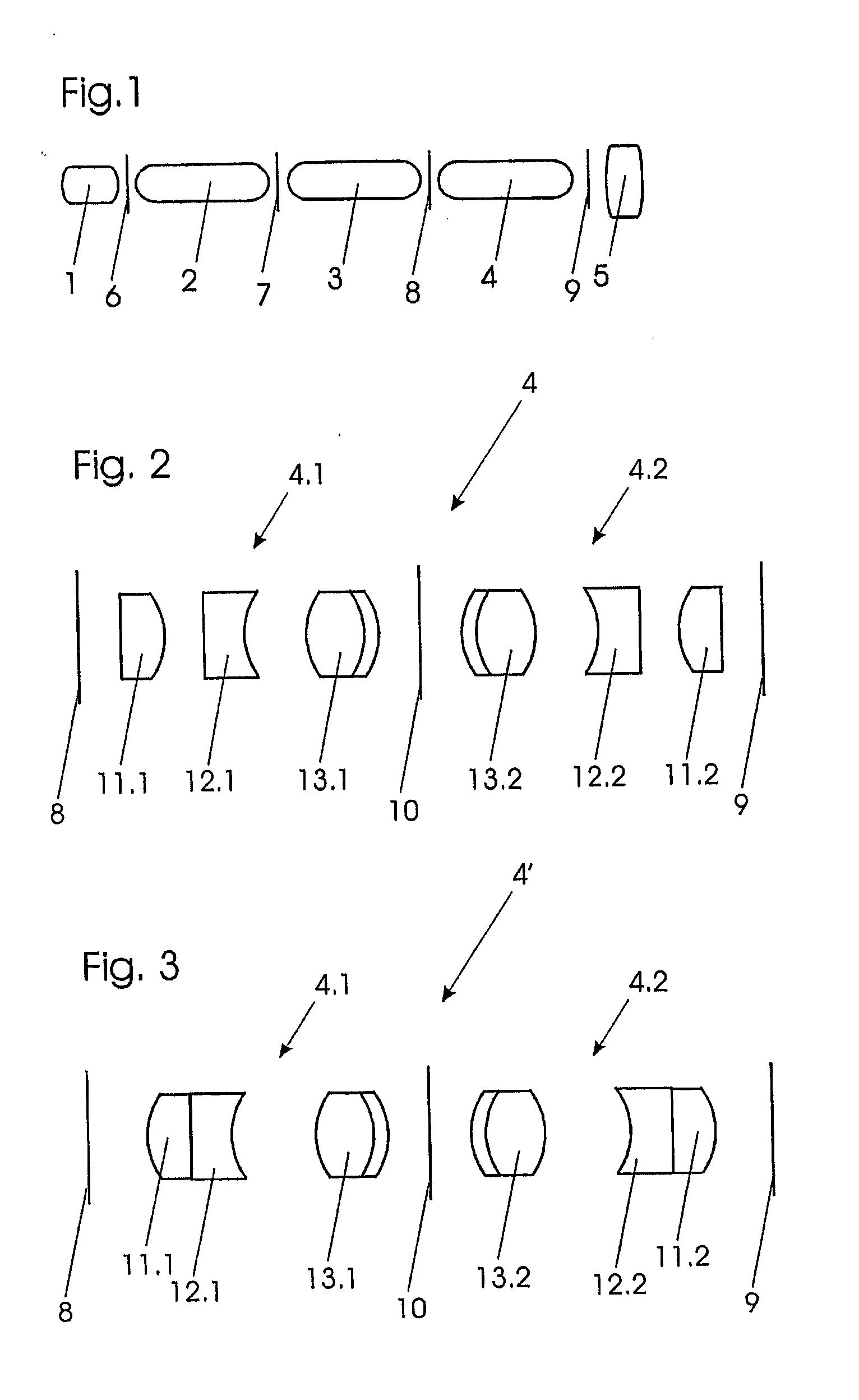
[0015]FIG. 1 shows the typical design of the optical system of a rigid endoscope. Within a rigid tube (not shown) the optical system is placed beginning at the distal end (in FIG. 1 to the left) with an objective 1. In the very schematic representation of FIG. 1 all lens units are shown as single lenses. In the proximal direction from the objective 1 there is following a first relay set 2, a second relay set 3 and a third relay set 4. An ocular 5 is placed at the proximal end.

[0016]The objective 1 is producing an image at an image plane 6 which is transferred by the relay set 2 to an image plane 7 and in the same way from the image plane 7 to an image plane 8 and finally to an image plane 9 on which the image is viewed by the ocular 5, instead of which, also, a camera can be placed. The objective 1 and, also, the relay sets 2, 3 and 4 turn the image upside down so that an odd number of relay sets, in the shown embodiment three relay sets, are used to have an upright image on the fin...


PUM


Abstract

A relay set (4, 4′) for the optical system of a rigid endoscope, the optical system including an objective (1) at the distal end, an ocular (5) at the proximal end and between them a relay lens system consisting of several relay sets (2, 3, 4), the relay set (4, 4′) consisting of two half sets (4.1, 4.2) having the same lens units (11.1, 12.1, 13.1; 11.2, 12.2 13.2) arranged symmetrically with respect to the center (10) of the set (4, 4′), each half set (4.1, 4.2) consisting of two positive power lens units (11.1, 13.1; 11.2, 13.2) at the ends and one negative power lens unit (12.1; 12.2) in the middle, is characterized in that each half set is of Triplet design.

Description

BACKGROUND OF THE INVENTION[0001]Rigid endoscopes usually have an optical system consisting of an objective, an ocular and between them a relay lens system consisting of several relay sets. Because the objective and each relay set is producing an image which is turned upside down, and because a standard endoscope should produce an upright image, usually an odd number of relay sets is used so that the image produced by the optical system is upright.[0002]For good image quality, the optical system of an endoscope should be well corrected for the major lens aberrations. Most of the aberrations are corrected by the symmetrical design of the relay set. But it is especially difficult to correct for curvature of field aberrations.[0003]U.S. Pat. No. 4,693,568 shows a low cost relay set of simple design having in each half set two lens units of positive power. The disadvantage of this design is that it cannot correct the curvature of field aberration.[0004]From U.S. Pat. No. 4,676,606, a re...

Claims


Application Information

Patent Timeline
Patent Type & Authority Applications(United States)
IPC IPC(8): G02B23/24
CPCG02B23/2446
Inventor TOMIOKA, MAKOTO
Owner OLYMPUS WINTER & IBE
Learn More