
Display device

a technology of display device and display screen, which is applied in the direction of instruments, non-linear optics, optics, etc., can solve the problem of costlyness of the display device as a whol

Active Publication Date: 2008-10-02
JAPAN DISPLAY WEST
View PDF3 Cites 28 Cited by
  • Summary
  • Abstract
  • Description
  • Claims
  • Application Information

AI Technical Summary

Benefits of technology

[0010]An advantage of some aspects of the invention is to provide a display device in which the distance between the two display panels can be altered by an inexpensive method.
[0014]With such feature, the front rim normally used in the display device will be constituted of thin metal sheet, which means that using such rear cover will enable the mechanical strength of the display device to be increased. When such rear cover is used, the control board and other items for display panel drive that are disposed on the rear face of the backlight can be protected from external forces. Also, since the rear cover, if used, is fixed to the front rim in such a way that the fixing position is alterable, there will be no need to alter the rear cover even if the interpanel distance is altered.
[0016]With such feature, the intermediate case is divided into two—a first and a second case—and a moire eliminating film is disposed between such two cases. Thereby, the moire phenomenon that arises between the first and second liquid crystal display panels can be satisfactorily curbed.
[0021]With such feature, a CNT-FED, that is, a single structural member, can be used to realize both the second display panel and the backlight, so that the display device as a whole can be rendered even thinner.

Problems solved by technology

Hence there is the problem that, due to such need to specially prepare extra cases, the display device as a whole becomes costly.

Method used


Image

  • Display device
  • Display device
  • Display device

Examples


first embodiment

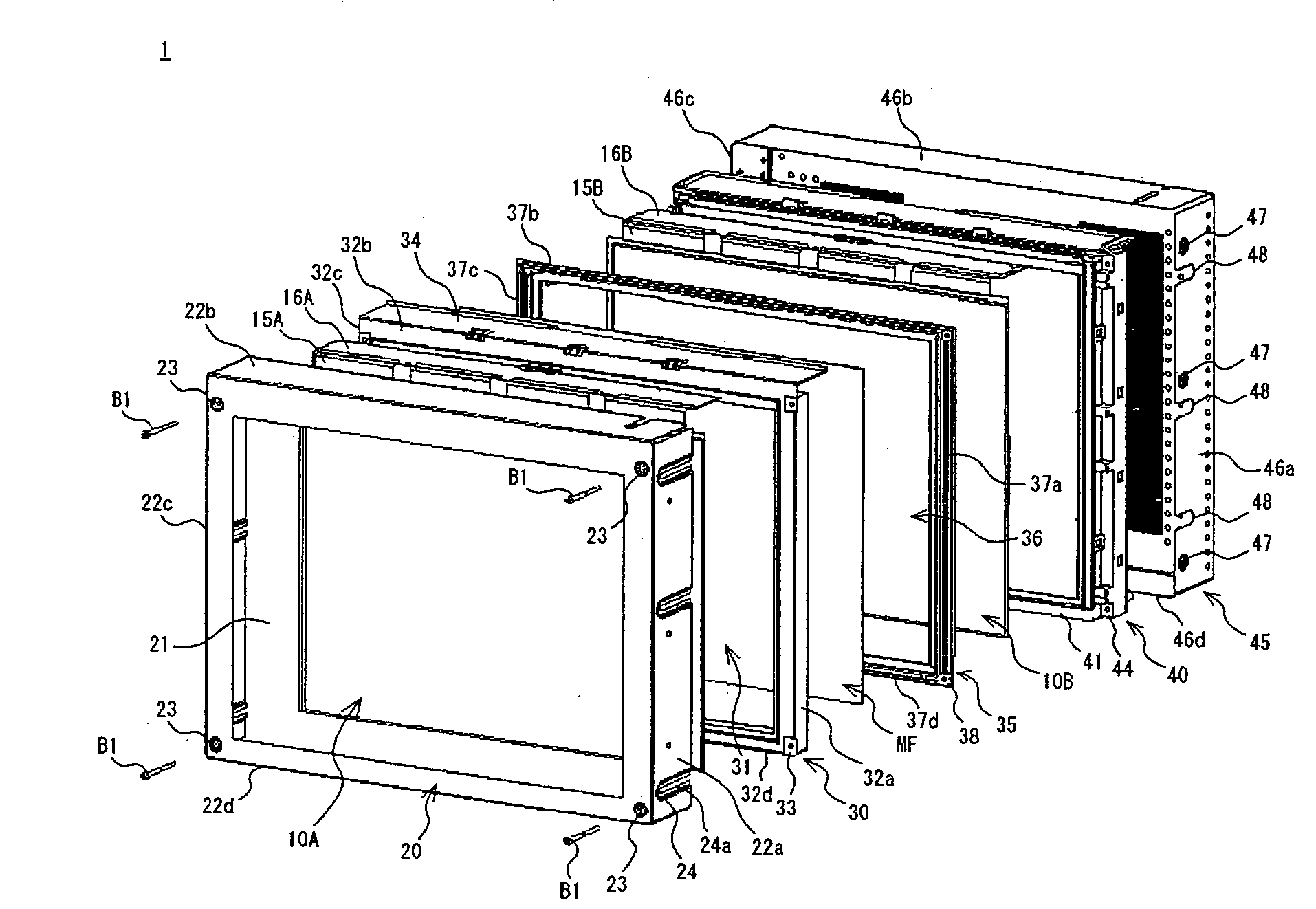
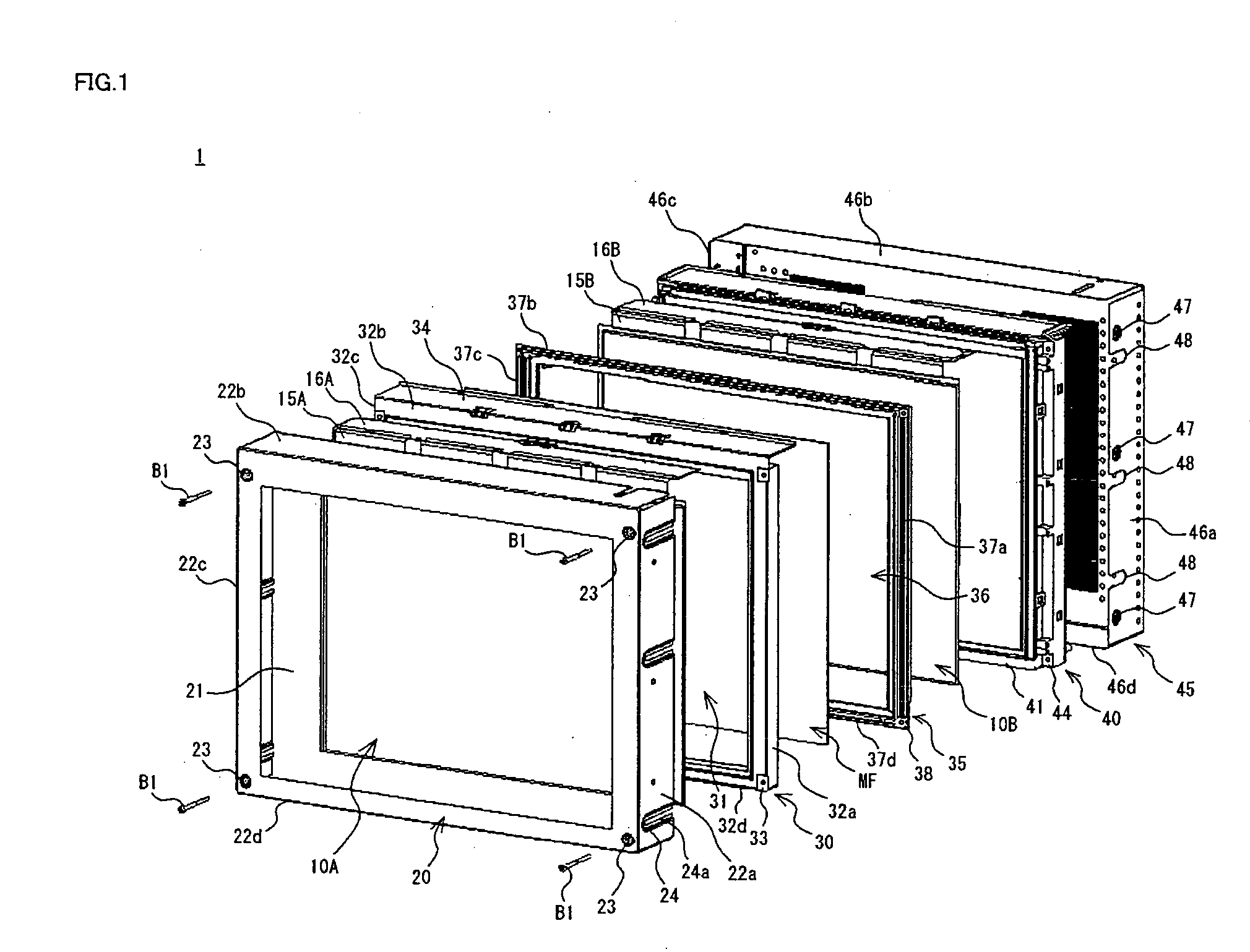
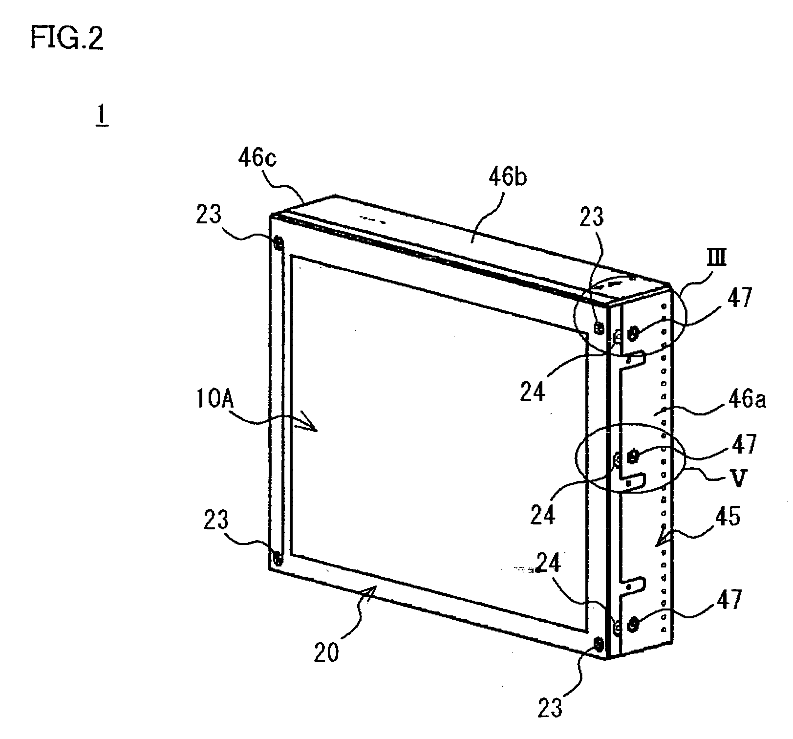
[0032]FIG. 1 is an exploded perspective view of a display device in a first embodiment of the invention, FIG. 2 is a perspective view illustrating display panels of FIG. 1 in the assembled state, FIG. 3 is an exploded schematic cross-sectional view of portion III in FIG. 2, FIG. 4 is a schematic cross-sectional view of the display device in FIG. 3 in the assembled state, and FIG. 5 is a schematic cross-sectional view of portion V in FIG. 2.

[0033]As FIGS. 1 and 2 show, a display device 1 of the invention is composed of: a first liquid crystal display panel 10A and second liquid crystal display panel 10B constituting first and second display panels; a front rim 20 that covers the periphery of the front of the first liquid crystal display panel 10A; first and second cases 30 and 35, plus a moire eliminating film MF, that form an intermediate case and are provided between the first and second liquid crystal display panels 10A, 10B; and a backlight 40 and rear cover 45 that are provided ...


PUM

PropertyMeasurementUnit
distanceaaaaaaaaaa
distancesaaaaaaaaaa
thicknessaaaaaaaaaa

Abstract

A display device 1 of an embodiment of the invention has a first display panel (10A), a second display panel (10B) that is disposed behind the first display panel (10A), a front rim 20 that is disposed in front of the first display panel (10A), an intermediate cases (30, 35) that are disposed between the first display panel (10A) and the second display panel (10B), and support the first display panel (10A) and the second display panel (10B), and a backlight 40 that is provided behind the second display panel (10B). At least the front rim 20, intermediate cases (30, 35) and backlight 40 are provided with fixing holes 23a, 33a, 38a, 44a in their corners, and fixing is effected integrally at each corner. Thanks to such structure, a display device is provided in which the distance between the two display panels can be altered by an inexpensive method.

Description

BACKGROUND[0001]1. Technical Field[0002]The present invention relates to a display device, and more particularly to a display device in which two display panels are superposed, in order to display images of diverse kinds, and the spacing between the two panels can be altered via simple structural means.[0003]2. Related Art[0004]Some display devices effect displays by deploying two display panels superposed, with the object of enhancing the stereoscopic effect or realism of the display screen. An example of such a display device is disclosed in JP-A-6-339575.[0005]FIG. 8 is a cross-sectional view of a display device of JP-A-6-339575, which is used in a pin-ball machine.[0006]The display device 100 disclosed in JP-A-6-339575, which is used in a pin-ball machine, is composed of two liquid crystal displays (LCDs) 101 and 102. As FIG. 8 shows, these two LCDs 101, 102 are well-known thin film transistor (TFT) type color LCDs, and are disposed in parallel, with the LCD 101 at the front, th...

Claims


Application Information

Patent Timeline
Patent Type & Authority Applications(United States)
IPC IPC(8): G02F1/1333
CPCG02F1/133308G02F1/13471G02F2201/46G02F1/133322
Inventor NISHIO, TOSHIYAISOO, JIRO
Owner JAPAN DISPLAY WEST
Learn More