
Elongated support apparatus for lifting an item to or supporting an item in an elevated condition

a support apparatus and elevated technology, applied in the direction of mechanical apparatus, machine supports, stand/trestle, etc., can solve the problems of accelerating fatigue, affecting the work efficiency of the individual, so as to achieve the effect of reducing fatigue and accelerating fatigu

Active Publication Date: 2022-02-15
ITOOL EQUIP HLDG
View PDF16 Cites 2 Cited by
  • Summary
  • Abstract
  • Description
  • Claims
  • Application Information

AI Technical Summary

Benefits of technology

The patent describes an apparatus for lifting items using a telescoping post assembly. The assembly has two opposite end sections, with an inner tube section and an outer tube section. The inner tube section moves within the outer tube section to change the distance between the two end sections. The apparatus also has a manually-operable actuator mechanism for adjusting the distance between the two end sections, which can be used to lift items from a support surface. The technical effect of this invention is a telescoping post assembly that can be easily and adjusted to lift items from different positions.

Problems solved by technology

Of course, the tasks of both holding the item in place and working upon or installing the item are likely to be too difficult for a single person to perform unless he has enough hands to accomplish these tasks simultaneously.
Furthermore, the item may have to be held in place for a lengthy period of time while the item is being worked upon or installed, and if such is the case, an individual who must hold the item in place may become unduly fatigued, and the fatigue may be accelerated if the item must be held overhead.

Method used


Image

  • Elongated support apparatus for lifting an item to or supporting an item in an elevated condition
  • Elongated support apparatus for lifting an item to or supporting an item in an elevated condition
  • Elongated support apparatus for lifting an item to or supporting an item in an elevated condition

Examples


embodiment 300

[0063]An example of a gas spring capable of being used as the motive means, generally indicated 324, of the embodiment 300 is available from Bansbach Easylift of North America, Inc. under the trade designation EASYLIFT.

[0064]To fixedly connect the inner and outer tubes 304 and 306 together, the tubes 304, 306 are arranged so that a selected opening 342 of the inner tube 304 is aligned with a selected opening 334 of the outer tube 306, and then the pin assembly 314 is utilized to pin the inner and outer tubes 304 and 306 together by way of the aligned openings 342, 344. Meanwhile, the outer tube 332 of the telescoping post assembly 322 is pinned to the inner tube 304 of the extension tube assembly 302 with a quick-release pin assembly 315 which is similar in construction to the pin assembly 314. Both of the pin assemblies 314 and 315, along with the attending openings 338, 342, 344 provided along the length of the tubes 322, 304 and 306, facilitate a prompt adjustment in the overall ...

embodiment 20

[0082]Furthermore and although the motive means 38 of the aforedescribed apparatus embodiment 20 of FIGS. 1-7 has been shown and described as being in the form of a gas spring 130, the motive means 38 can take an alternative form. For example, the motive means of an apparatus embodying features of the present invention could be provided by a battery-powered linear actuator for moving the two opposite ends of a telescoping post assembly toward or away from one another. Within such an embodiment, a manually-operable actuator mechanism could be provided by the switching mechanism of a two position switch.

[0083]Further still, an actuator mechanism suitable for use with an apparatus of the present invention need not be manually manipulated at the telescoping tube assembly of the apparatus. Instead, such an actuator mechanism could be manipulated remotely (e.g. with appropriate electronic hardware) of the telescoping tube assembly. Accordingly, the aforedescribed embodiments are intended ...


PUM


Abstract

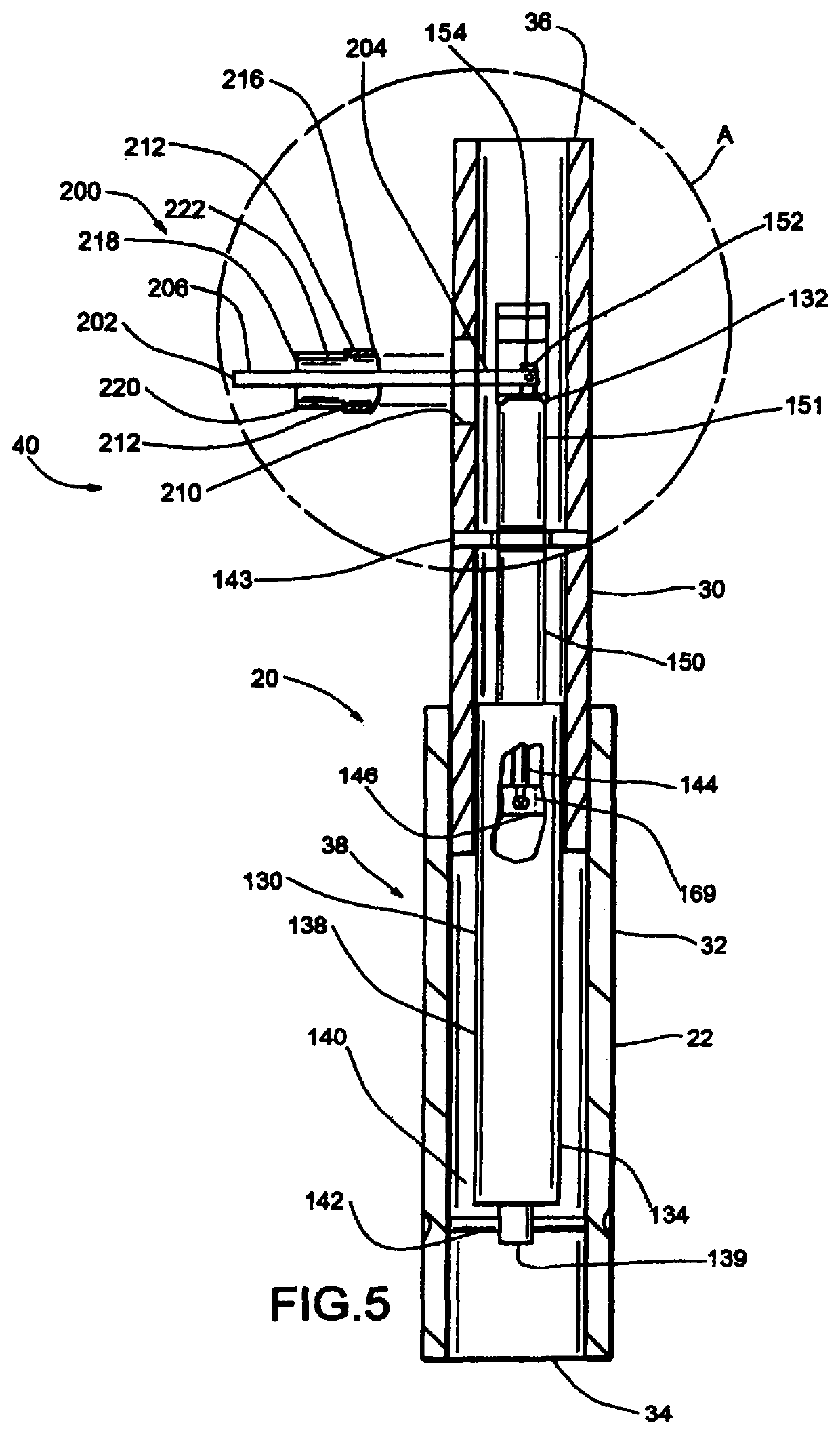
An apparatus for lifting or supporting an item in an elevated condition includes a telescoping post assembly having an inner tube section which provides one end section of the post assembly and an outer tube section which defines an opposite end section of the post assembly. In addition, a gas spring is mounted within the post assembly for acting between the inner and outer tube sections, and a manually-operable lever member is associated with the gas spring and is cooperable with a fulcrum member to effect the movement of the two opposite end sections of the post assembly away from one another so that by positioning the telescoping post assembly between the support surface and the item to be lifted and then moving the actuator mechanism between two conditions effects the lifting of the item from the support surface.

Description

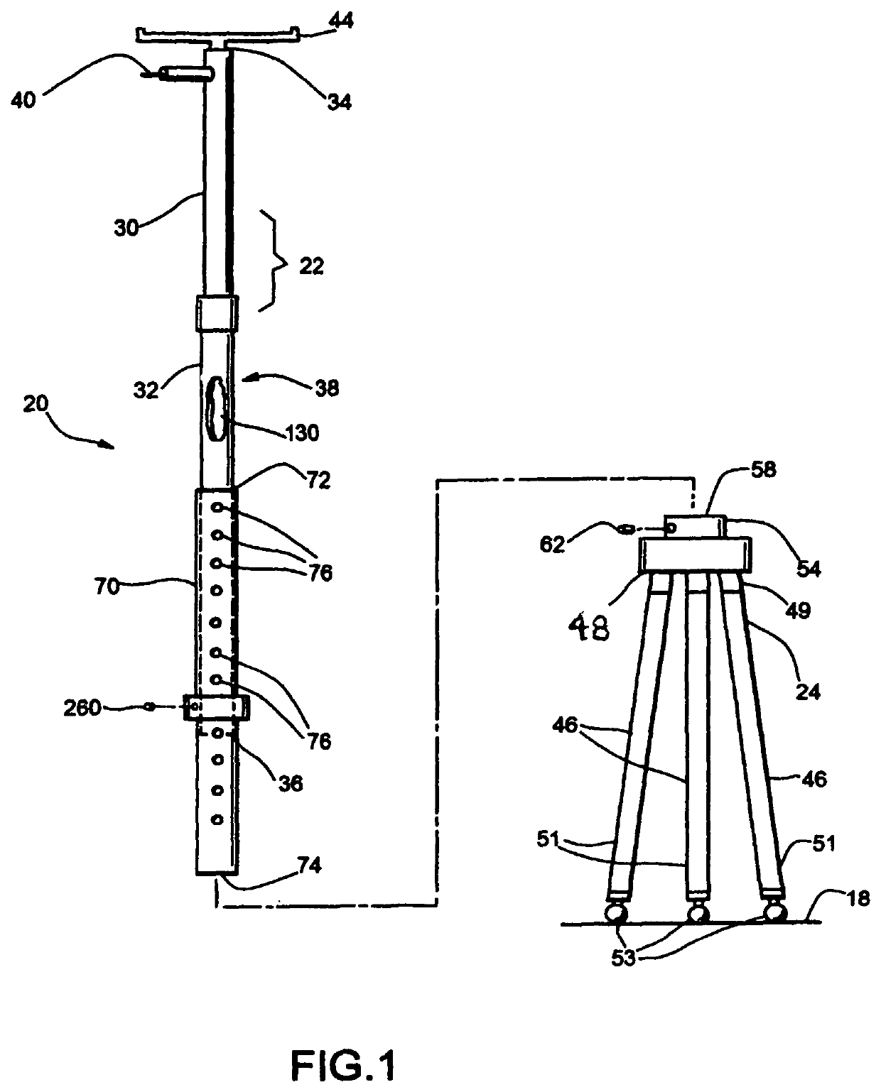
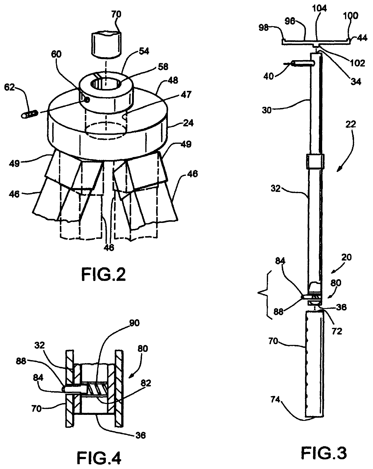
BACKGROUND OF THE INVENTION[0001]This invention relates generally to apparatus for lifting and supporting an item and relates, more particularly, to such apparatus which facilitates the lifting and support of an item in an elevated condition above an underlying floor while the item is being worked upon or installed.[0002]The task of working upon or installing an item, such as a light fixture or ceiling ductwork or conduit, in an overhead environment often requires that the item be held in place while it is being worked upon or installed. Of course, the tasks of both holding the item in place and working upon or installing the item are likely to be too difficult for a single person to perform unless he has enough hands to accomplish these tasks simultaneously. Furthermore, the item may have to be held in place for a lengthy period of time while the item is being worked upon or installed, and if such is the case, an individual who must hold the item in place may become unduly fatigued...

Claims


Application Information

Patent Timeline
Patent Type & Authority Patents(United States)
IPC IPC(8): F16M11/28
CPCF16M11/28F16M2200/028
Inventor JORDAN, DAVID S.JORDAN, MICHAEL C.JORDAN, SCOTT M.
Owner ITOOL EQUIP HLDG
Learn More