
Light-emitting device

a light-emitting device and light-emitting technology, which is applied in the field of light-emitting devices, can solve the problems of complicated manufacturing process lower light coupling efficiency of organic light-emitting devices, and cathode ray tubes, etc., and achieves the effects of improving light coupling efficiency, color purity, and durability

Active Publication Date: 2008-10-02
SAMSUNG DISPLAY CO LTD +1
View PDF13 Cites 33 Cited by
  • Summary
  • Abstract
  • Description
  • Claims
  • Application Information

AI Technical Summary

Benefits of technology

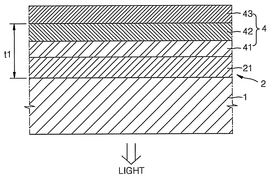
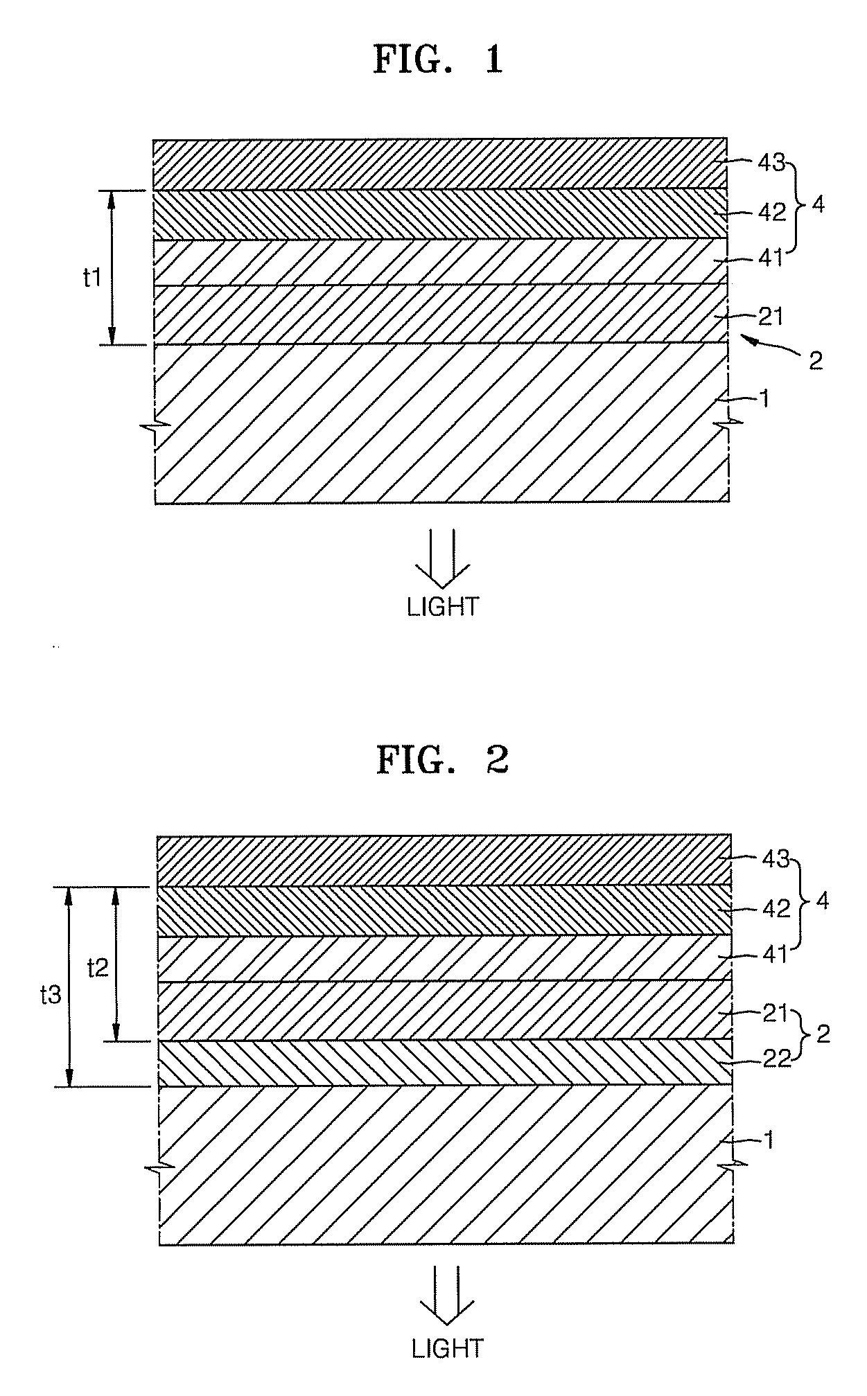
[0008]Aspects of the present invention provide a light-emitting device, which can be easily manufactured, and has improved light coupling efficiency, color purity, durability, etc., by virtue of an improved optical resonance layer.
[0010]The light-emitting device can have high light coupling efficiency and color purity. In addition, the optical resonance layer has a high mechanical strength, thereby improving the durability of the light-emitting device.

Problems solved by technology

Organic light-emitting devices have a lower light coupling efficiency than other devices, such as, cathode ray tubes, and plasma display panels (PDPs).
However, in order to adjust the reflectance of the translucent mirror for a predetermined wavelength, it is necessary to accurately design the number and thicknesses of the layers constituting the translucent mirror, which complicates the manufacturing process of an organic light-emitting device.

Method used


Image

  • Light-emitting device
  • Light-emitting device
  • Light-emitting device

Examples


synthesis example 1

[0094]8.865 g of methyl trimethoxysilane (MTMS) and 3.406 g of bis(triethoxysilyl)ethane (BTESE) (the molar ratio of MTMS to BTESE was 5:5) were dissolved in 26.831 g of THF, used as a solvent, and a diluted solution, of 0.75 ml of 2N HCl in 8.31 g of water as a catalyst, was gradually added thereto. The concentration of the monomers MTMS and BTESE was adjusted to 30 wt %, and the total amount of the monomers MTMS and BTESE was adjusted to 0.05 moles. In the resultant products, the ratio of —OH to an alkoxy group was measured by NMR, to determine a binding ratio of MTMS to BTESE. The NMR results showed the synthesis of polysilsesquioxane-based copolymers having a weight average molecular weight of about 5100, and a number average molecular weight of 2750, in which —O—, —CH2— and —CH2CH2— were present as linking groups between two different silicon atoms, and a methoxy group, a methyl group, an ethoxy group, and a hydroxyl group were present as end groups. The NMR results were as fol...

synthesis example 2

[0096]Polysilsesquioxane-based copolymers (weight average molecular weight: 4200, number average molecular weight: 2200) were synthesized in the same manner as in Synthesis Example 1, except that the molar ratio of MTMS to BTESE was adjusted to 9:1.

synthesis example 3

[0097]Polysilsesquioxane-based copolymers (weight average molecular weight: 8600, number average molecular weight: 2350) were synthesized in the same manner as in Synthesis Example 1, except that the molar ratio of MTMS to BTESE was adjusted to 8:2.


PUM


Abstract

A light-emitting device including: a substrate; a light-emitting diode; and an optical resonance layer to resonate light emitted from the light-emitting diode. The optical resonance layer includes a first layer, including a polysilsesquioxane-based copolymer. A linking group connecting two different silicon (Si) atoms of the polysilsesquioxane-based copolymer can be —O—, or a substituted or unsubstituted C1-C30 alkylene group.

Description

CROSS-REFERENCE TO RELATED APPLICATION[0001]This application claims the benefit of Korean Application No. 2007-31085, filed Mar. 29, 2007, in the Korean Intellectual Property Office, the disclosure of which is incorporated herein by reference.BACKGROUND OF THE INVENTION[0002]1. Field of the Invention[0003]Aspects of the present invention relate to a light-emitting device, and more particularly, to a light-emitting device including an optical resonance layer including a polysilsesquioxane-based copolymer.[0004]2. Description of the Related Art[0005]The light efficiency of light-emitting devices, such as, liquid crystal displays, or organic light-emitting devices, is divided between an internal efficiency and an external efficiency. The internal efficiency depends on the photoelectric conversion efficiency of a light-emitting material. The external efficiency, which is also called the “light coupling efficiency”, depends on the refractive index of each layer constituting the light-emi...

Claims


Application Information

Patent Timeline
IPC IPC(8): H01L33/00
CPCH01L27/3211Y10S428/917H01L51/5265H10K59/35H10K59/876H05B33/22H05B33/20H10K50/852
Inventor LEE, SUN-YOUNGLEE, JONG-HYUKSONG, YOUNG-WOOLEE, JOON-GULEE, SO-YOUNGYOON, DO-YOUNG
Owner SAMSUNG DISPLAY CO LTD
Learn More