
Actuator Control Unit and Electric-Mechanical Brake Unit

a technology of electric-mechanical brake unit and actuator control unit, which is applied in the direction of braking system, coupling device connection, substation/switching arrangement casing, etc., can solve the problem of hard to form a space between the pedestal and the connection of flat cables, and achieve the effect of downsizing the actuator control uni

Active Publication Date: 2008-10-02
HITACHI ASTEMO LTD
View PDF13 Cites 7 Cited by
  • Summary
  • Abstract
  • Description
  • Claims
  • Application Information

AI Technical Summary

Benefits of technology

The present invention relates to an actuator control unit and an electric-mechanical brake unit. The technical effect of the invention is to achieve a further downsizing of the actuator control unit by embedding a bus bar in a circuit mounting case and exposing part of it to the outer portion of the case. The bus bar is embedded in the circuit mounting case and partially exposed on one side surface in a wiring direction. The actuator control unit has a control circuit controlling an actuator and a bus bar electrically connected to the control circuit. The bus bar is embedded in the circuit mounting case and partially exposed on one side surface in a wiring direction. The actuator control unit has a circuit mounting case with a projection portion that has a greater height than the embedded portion of the bus bar. The bus bar is welded to other terminals in the actuator control unit. The actuator control unit has a projection portion in an inverse side to the first projection portion in the circuit mounting case. The circuit mounting case has a projection portion that has a surface that is orthogonal to the wiring direction of the bus bar. The actuator control unit has an inverter element module and a control board connected to the bus bar. The actuator control unit has an external shielding metal case assembled in the circuit mounting case and a harness electrically connecting the connector portion of the circuit mounting case and an external electric circuit.

Problems solved by technology

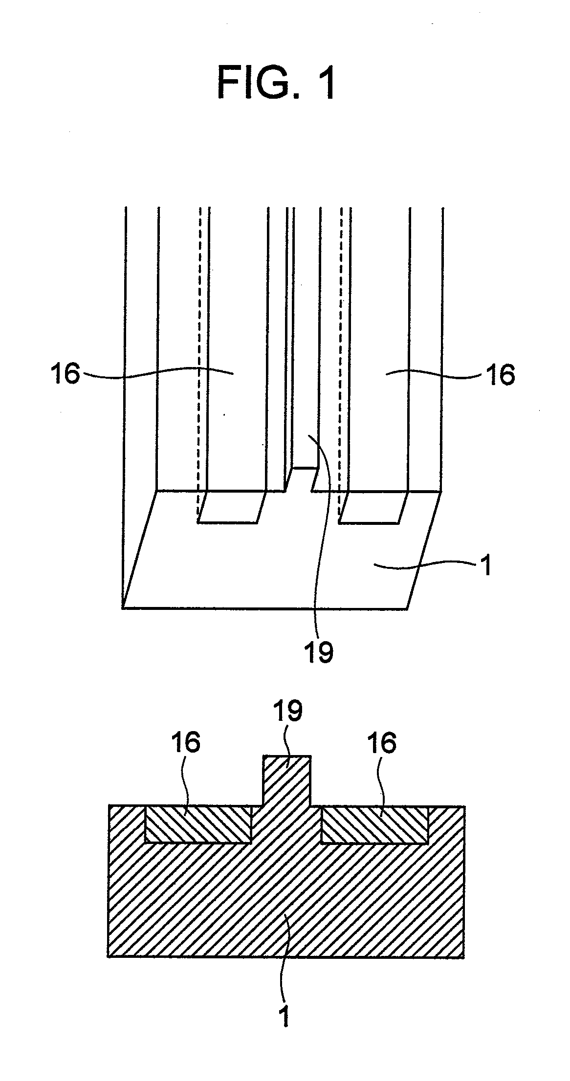
However, since the prior art is structured such that the bus bar is embedded in an inner portion of the resin, a space for fluidizing the resin is necessary around the bus bar, and it is hard to form a space between a pedestal for a flat cable to be connected, and the bus bar.

Method used


Image

  • Actuator Control Unit and Electric-Mechanical Brake Unit
  • Actuator Control Unit and Electric-Mechanical Brake Unit
  • Actuator Control Unit and Electric-Mechanical Brake Unit

Examples


Embodiment Construction

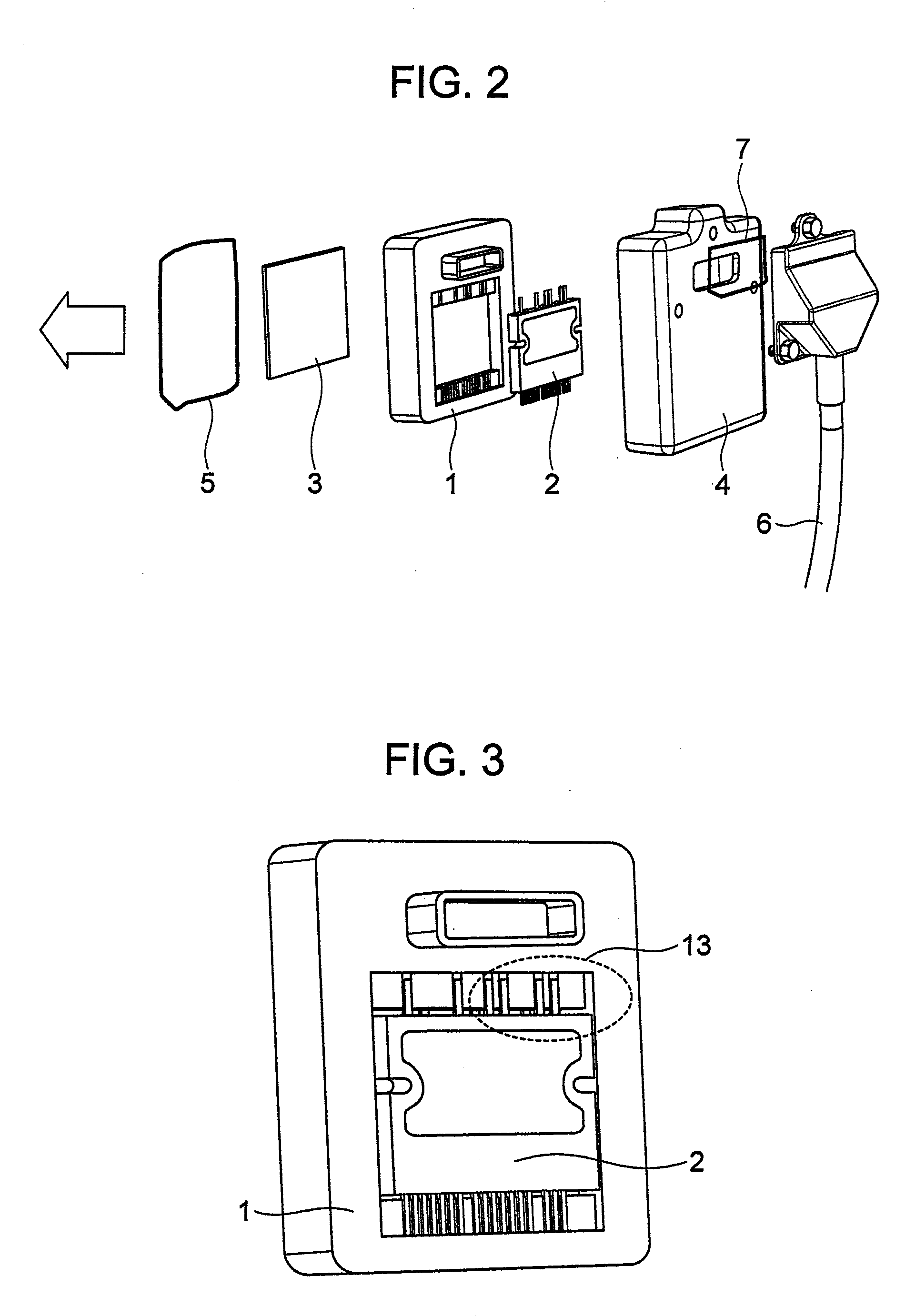
[0061]FIG. 2 is an exploded perspective view of an actuator integrated type control unit.

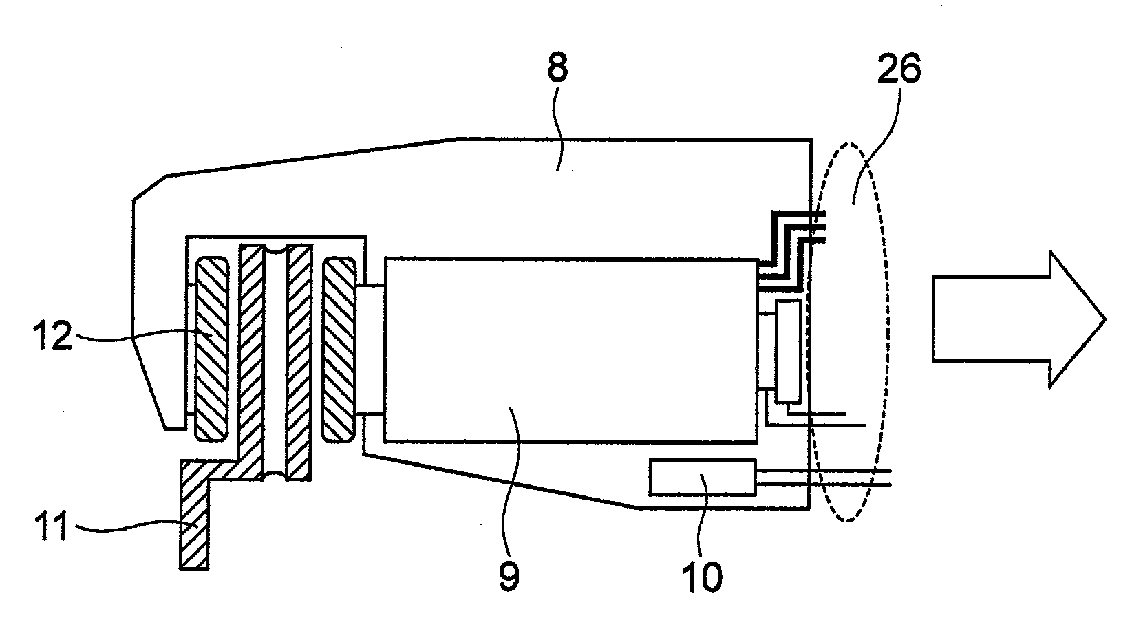
[0062]In this embodiment, a control board 3 controlling an actuator and an inverter element module 2 driving the actuator are mounted to a resin case 1 serving as a circuit mounting case, and a connecting portion therebetween is connected to a bus bar wired within the resin case 1, whereby an electric circuit is constructed. The control board 3 is connected to the bus bar wired within the resin case 1, for example, in accordance with an aluminum wire bonding. The inverter element module 2 is connected to the bus bar wired within the resin case 1, for example, in accordance with a welding between terminals. The electric circuit structured as mentioned above is connected to an electric circuit in an external portion by exposing the bus bar wired within the resin case 1 to a connector shaped portion of the resin case 1 and connecting the exposed portion to a connector of a harness 6.

[0063]In this c...


PUM


Abstract

The invention achieves a further downsizing of an actuator control unit. The actuator control unit has a control circuit controlling an actuator, and a bus bar electrically connected to the control circuit and arranged such as to be partially embedded in an inner portion of a resin case and be partially exposed to an outer portion of the resin case. It is preferable to have a projection portion extending in a wiring direction of the bus bar between two bus bars wired adjacently, having a greater height than an embedded plane of the bus bar in the resin case, and made of an insulating material.

Description

BACKGROUND OF THE INVENTION[0001]1. Field of the Invention[0002]The present invention relates to an actuator control unit.[0003]2. Background Art[0004]The actuator control unit has become compact year by year. In particular, constructing a solid circuit by arranging a metal conductive plate such as a bus bar or the like so as to achieve a reduction of a mounting area of a connoted board greatly contributes to a downsizing of the control unit.[0005]There has been conventionally known a unit which is mainly provided with bus bars transmitting an electronic signal and an electric power, a resin for insulating between the bus bars and the like as the other structure bodies than the circuit board, and arranges the bus bars while covering with an insulating material (refer, for example, to patent document 1 (JP-A-2000-156922 and patent document 2 (JP-A-2002-359020)).[0006]The inventors of the present invention have considered to further downsize the structure body of the actuator control ...

Claims


Application Information

Patent Timeline
Patent Type & Authority Applications(United States)
IPC IPC(8): H02B1/26F16D65/14
CPCB60T13/741H01R13/6215H01R13/5219
Inventor YASUKAWA, DAISUKEWATANABE, HIROFUMI
Owner HITACHI ASTEMO LTD
Learn More