Electric locomotive traction system

A technology for traction systems and electric locomotives, applied in the direction of electric locomotives, AC induction motor traction, locomotives, etc., can solve the problems of large structure, complex structure, and large space occupation, so as to improve stability and reliability and reduce control units , The effect of reducing system cost

Active Publication Date: 2016-04-06
CRRC YONGJI ELECTRIC CO LTD
View PDF4 Cites 0 Cited by
  • Summary
  • Abstract
  • Description
  • Claims
  • Application Information

AI Technical Summary

Problems solved by technology

It can be seen that in the existing traction system, each set of traction converters is set separately, the structure is complex, it takes up a lot of space, and the cost is high, and each set of traction converters needs to be equipped with a separate controller, which is not conducive to the traction system. control, the consistency of the electrical performance of the traction system is poor; the auxiliary converter is installed separately in the auxiliary converter cabinet, which will occupy a large space, and the structure occupies a large space; at the same time, the traction transformer used in conjunction with the system , it is necessary to set up 6 secondary windings, which makes the traction transformer complex in structure and high in cost
[0004] To sum up, in the existing AC drive electric locomotive traction system, the traction converters connected to the asynchronous traction motors are set up separately, each traction converter needs to be equipped with a controller, and the entire AC drive electric locomotive traction system needs to be equipped with 3 traction converter cabinet, the circuit integration in the traction system is low, the structure is huge, and the cost is high; at the same time, 6 sets of traction converters are set independently, which will make the consistency of the electrical performance of each traction converter poor, affecting the traction Stability and reliability of system work

Method used


Image

  • Electric locomotive traction system
  • Electric locomotive traction system

Examples


Embodiment Construction

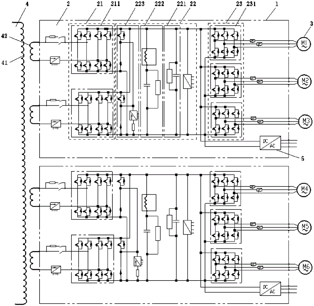
[0017] figure 2 It is a schematic structural diagram of an electric locomotive traction system provided by an embodiment of the present invention. like figure 2 As shown, the electric locomotive traction system of this embodiment includes: two traction converter cabinets 1, each traction converter cabinet 1 is respectively provided with a set of traction converters 2; each traction converter 2 includes sequentially electrically connected A rectifier circuit 21, an intermediate DC transmission circuit 22 and an inverter circuit 23, wherein the rectifier circuit 21 includes two sub-rectifier circuits 211 connected in parallel, and the inverter circuit 23 includes three sub-inverter circuits 231 connected in parallel; The output terminals of the inverter circuit are respectively connected with asynchronous traction motors 3 . The electric locomotive traction system in this embodiment has two traction converter cabinets, and the three sub-inverter circuits in each traction con...


PUM


Abstract

The invention provides an electric locomotive traction system. The electric locomotive traction system comprises two traction current conversion cabinets, and each traction current conversion cabinet is provided with a set of traction converter. Each traction converter comprises a rectifier circuit, an intermediate direct current transmission circuit and an inverter circuit, wherein the rectifier circuit, the intermediate direct current transmission circuit and the inverter circuit are in electric connection sequentially. The rectifier circuit comprises two secondary rectifier circuits connected in parallel, the inverter circuit comprises three secondary inverter circuits connected in parallel, and output ends of the secondary inverter circuits are respectively connected with an asynchronous traction motor. The electric locomotive traction system is compact in structure and low in cost.

Description

technical field [0001] The invention relates to electric locomotive traction technology, in particular to a high-power AC drive electric locomotive traction system. Background technique [0002] AC drive traction technology is the traction technology commonly used on electric locomotives at present. It uses alternating current to drive the motor on the locomotive to work. Among them, the electric locomotive traction system mainly transforms, rectifies and inverts the high-voltage alternating current transmitted by the grid. , to provide AC drive voltage for the motor. [0003] figure 1 It is a structural schematic diagram of an existing AC drive electric locomotive traction system. like figure 1 As shown, the main circuit of the existing electric locomotive traction system includes 6 sets of independent traction converters 10, and each set of traction converters 10 consists of a four-quadrant rectifier 101, an intermediate DC transmission circuit 102 and a three-phase inv...

Claims


Application Information

Patent Timeline
Patent Type & Authority Patents(China)
IPC IPC(8): B61C3/00B60L9/24
CPCY02T10/72
Inventor 陈广泰高永军王彬姜新生刘佳岳文开韩建宁贾云岗
Owner CRRC YONGJI ELECTRIC CO LTD
Why Eureka
Try Eureka