
Humeral head augment device and method for use in a shoulder prosthesis

a technology of humeral head and shoulder, which is applied in the field of orthopaedic implants, can solve the problems of shoulder arthroplasty, shoulder joint overstuffing, and needing to undergo a shoulder arthroplasty procedur

Active Publication Date: 2008-09-25
HOWMEDICA OSTEONICS CORP
View PDF12 Cites 19 Cited by
  • Summary
  • Abstract
  • Description
  • Claims
  • Application Information

AI Technical Summary

Benefits of technology

[0007]The present invention provides in another aspect, a modular shoulder prosthesis that includes a humeral head that has an articulation surface and an interior surface from which a connector extends and a stem component that includes a second connector that engages the humeral head and secures the two components together. The shoulder prosthesis further includes a humeral head augment device that has an external bearing surface with at least one surface portion having a radius of curvature and a coupling mechanism that is configured to connect the humeral head augment device to either the stem or humeral head. When the humeral head augment device is attached to the implanted shoulder prosthesis, the at least one radius of curvature of the external bearing surface functions to constrain translation of the shoulder prosthesis post-operatively.
[0008]The present invention provides in yet another aspect, a shoulder prosthesis system. The shoulder prosthesis system includes a plurality of humeral heads, each having an articulation surface and an interior surface that has a connector extending from it. In addition, the system includes a plurality of stems, the stems each having a proximal end that includes a connector for engaging the connector disposed on the interior surface of the humeral head. The shoulder prosthesis system further includes a plurality of humeral head augment devices, each humeral head augment device having an external bearing surface that is configured with at least one surface portion that has a radius of curvature. Each of the humeral head augment devices also include a coupling mechanism that operates to connect the humeral head augment device to either one of the plurality of stems or one of the plurality of humeral heads. When assembled within the shoulder prosthesis, the humeral head augment device functions to constrain translational movement of the shoulder prosthesis following implantation.

Problems solved by technology

Deterioration of an individual's rotator cuff may lead to the need to undergo a shoulder arthroplasty procedure.
Articulation between these two bones could lead to accelerated destruction of the humeral head and erosion of the acromion and the acromioclavicular joint.
Both of these treatment modalities led to the overstuffing of the joint space and a resultant reduced range of motion for the effected arm of the individual.
Several non-implant surgical techniques have been used with limited success in an attempt to address the rotator cuff tear arthropathy, including surgically smoothing the greater tubercle.
Unfortunately, the individual still experienced reduced range of motion and joint pain because of the bone on bone contact.
Problems that have been seen with these types of designs is excessive post-operative translation in the superior direction because of the previous bone loss and the use of a single radius of curvature for the two bearing portions.
Another problem encountered with the extended bearing modular humeral heads is the head being incorrectly rotated when the prosthesis is assembled in the operating room.

Method used


Image

  • Humeral head augment device and method for use in a shoulder prosthesis
  • Humeral head augment device and method for use in a shoulder prosthesis
  • Humeral head augment device and method for use in a shoulder prosthesis

Examples


Embodiment Construction

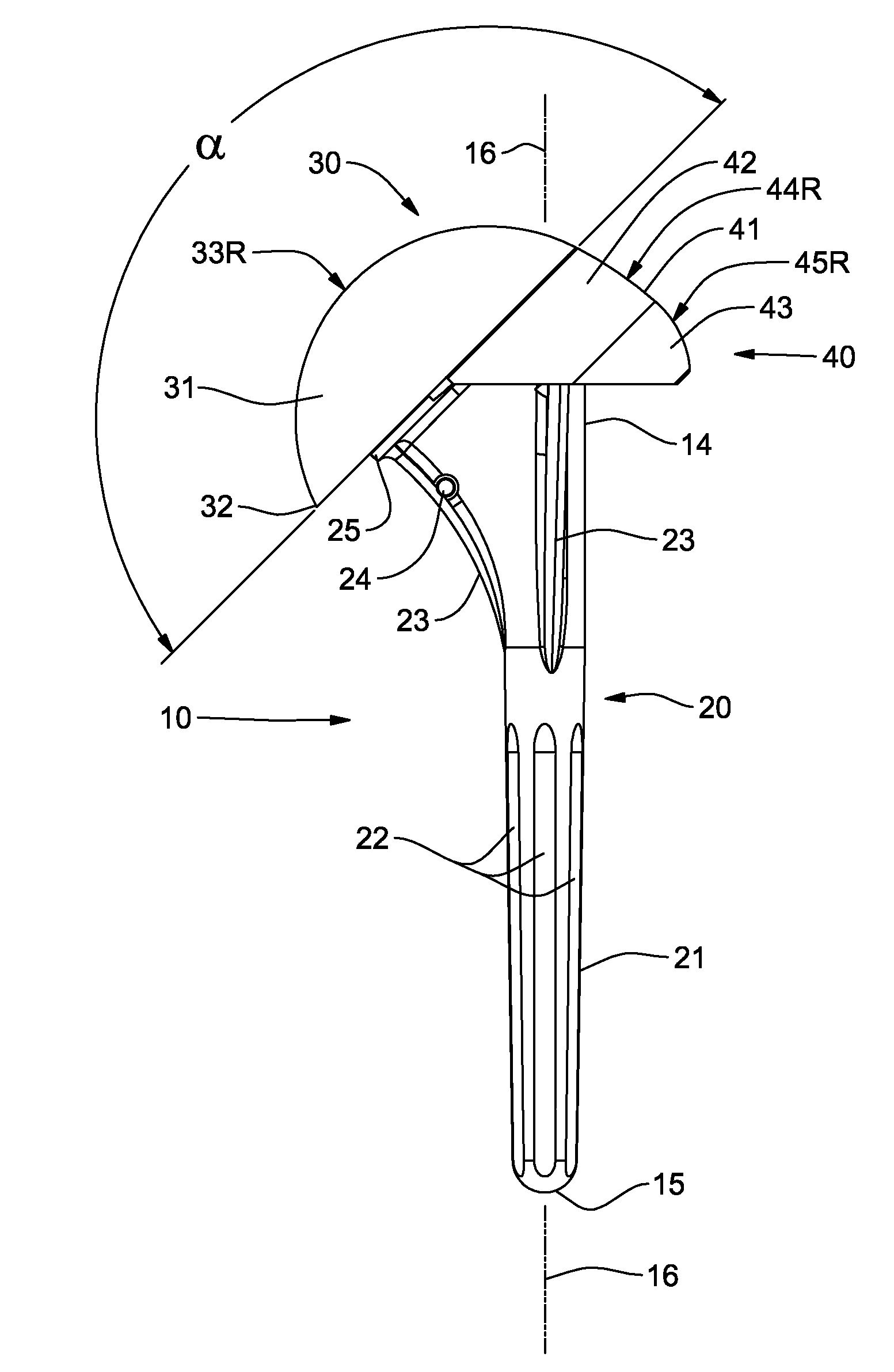
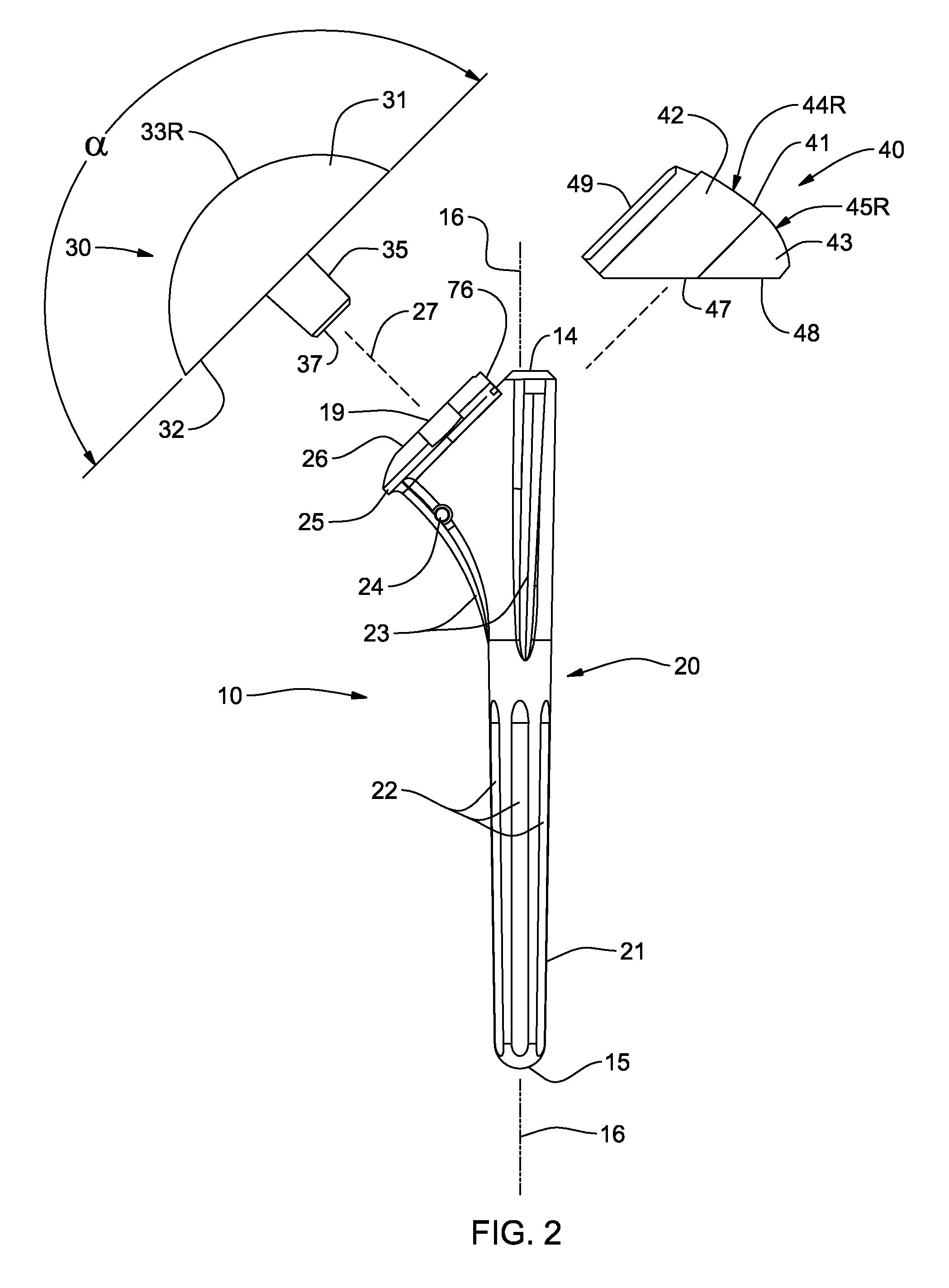
[0029]Generally stated, disclosed herein is a humeral head augment device and a shoulder prosthesis that includes as a component, a humeral head augment device. Further, described herein is a method for using a humeral head augment device with a shoulder prosthesis that may limit post-operative translateral movement for patients suffering from rotator cuff arthopathy.

[0030]As depicted in FIGS. 1 and 2, the general arrangement of a shoulder prosthesis 10 for use with a humeral head augment device 40, in accordance with an aspect of the present invention, includes a humeral head 30, a stem 20 and a humeral head augment device 40. In this detailed description and the following claims, the words proximal, distal, anterior, posterior, medial and lateral are defined by their standard usage for indicating a particular part of a bone or prosthesis according to the relative disposition of the natural bone or directional terms of reference. For example, “proximal” means the portion of a prost...


PUM

PropertyMeasurementUnit
Radiusaaaaaaaaaa
Distanceaaaaaaaaaa
Biocompatibilityaaaaaaaaaa

Abstract

A humeral head augment device for use in a modular shoulder prosthesis. The humeral head augment device has an external bearing surface with at least one surface portion that includes a radius of curvature. The radius of curvature is configured to constrain translational movement of the implanted shoulder prosthesis when the humeral head augment device is positioned within the shoulder prosthesis. The humeral head augment device also includes a coupling mechanism designed to lock the humeral head augment device to either the stem or the humeral head, thereby ensuring proper operational positioning of the device within the shoulder prosthesis and allowing the implanted shoulder prosthesis to function in a patient suffering from rotator cuff arthropathy. A shoulder prosthesis using a humeral head augment device, a method for assembling a shoulder prosthesis and method for using a humeral head augment device in a shoulder prosthesis are also disclosed.

Description

TECHNICAL FIELD[0001]The present invention relates generally to orthopaedic implants. More particularly, the present invention relates to a shoulder replacement prosthesis and the method of use for treating rotator cuff arthropathy.BACKGROUND OF THE INVENTION[0002]Deterioration of an individual's rotator cuff may lead to the need to undergo a shoulder arthroplasty procedure. In severe cases, a person's humeral head may translate in a more superior direction during abduction of their effected arm resulting in the superior surface of the humeral head articulating with both the inferior surface of the acromion and the acromioclavicular joint. Articulation between these two bones could lead to accelerated destruction of the humeral head and erosion of the acromion and the acromioclavicular joint.[0003]It was generally accepted practice for orthopedic surgeons to treat individuals with compromised rotator cuffs using standard sized shoulder stem prosthesis with oversized humeral heads to...

Claims


Application Information

Patent Timeline
IPC IPC(8): A61F2/40
CPCY10T29/49947A61F2002/4037A61F2/4014A61F2002/4033A61F2002/4062A61F2002/4018
Inventor MUTCHLER, AUSTIN W.CHURCHILL, R. SEAN
Owner HOWMEDICA OSTEONICS CORP
Learn More