
Multiple-Output DC-DC Converter

a dc-dc converter and multi-output technology, applied in the direction of dc-dc conversion, dc-dc network circuit arrangement, ac network voltage adjustment, etc., can solve the problem that the converter cannot stay out of the trend, the loss of power transistors is more serious, and the control method is not practical and practicabl

Inactive Publication Date: 2008-09-25
JDA TECH
View PDF12 Cites 177 Cited by
  • Summary
  • Abstract
  • Description
  • Claims
  • Application Information

AI Technical Summary

Benefits of technology

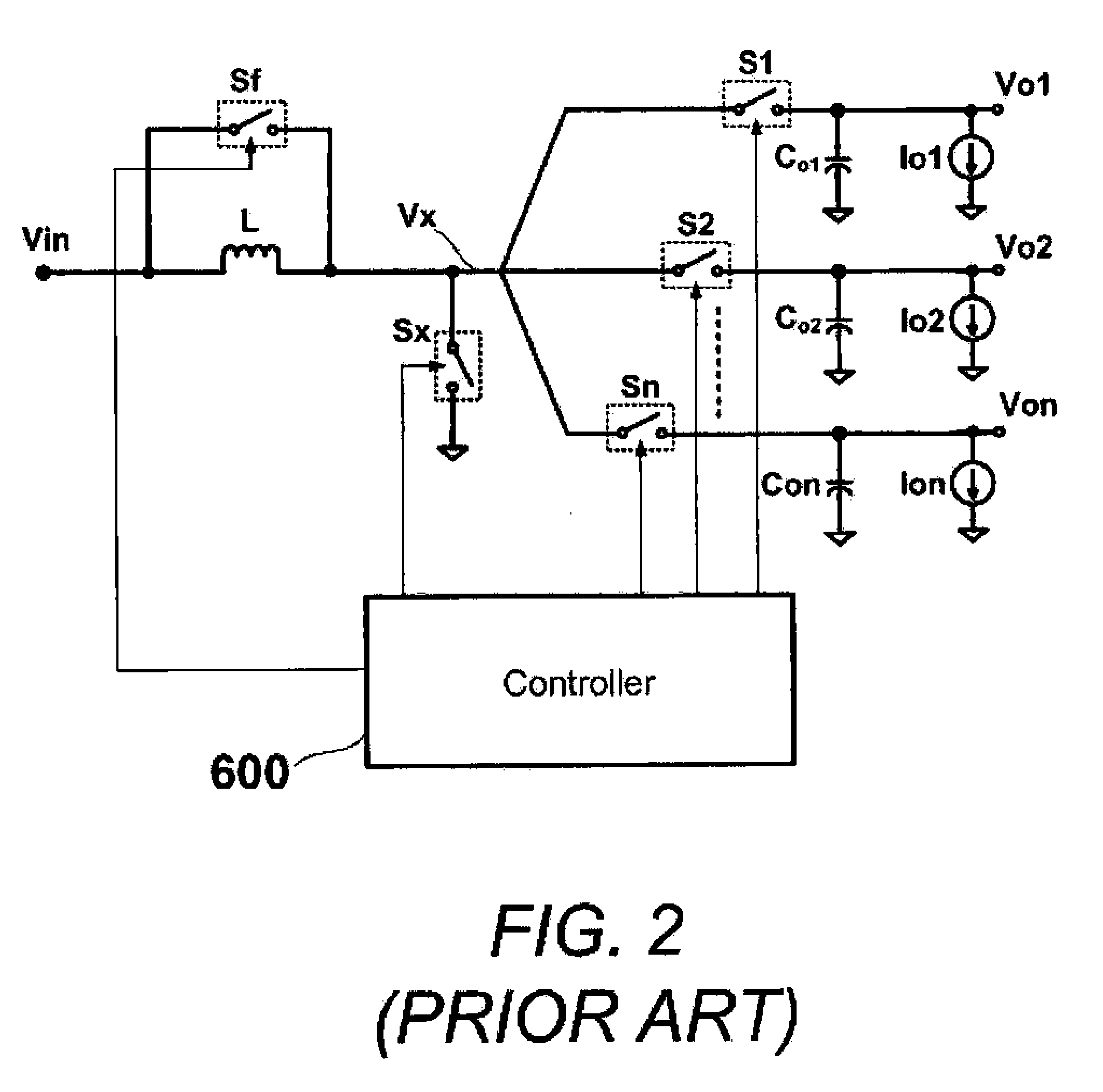
[0006]A multiple-output DC-DC converter is provided by the present invention which comprises an inductor for storing energy, a charging switch electrically connected in series with the inductor, a plurality of N output switches, wherein first ends of the output switches are connected to a node between the inductor and the charging switch and second end of each output switch is connected to a corresponding output terminal, wherein N is an integer of two or more, ...

Problems solved by technology

As all designs are put into an effort of size reduction, converter cannot stay out of that trend.
However, it is still a big challenge to DC-DC converter designers because before the disclose of this invention, there is no proper control method that can be practical.
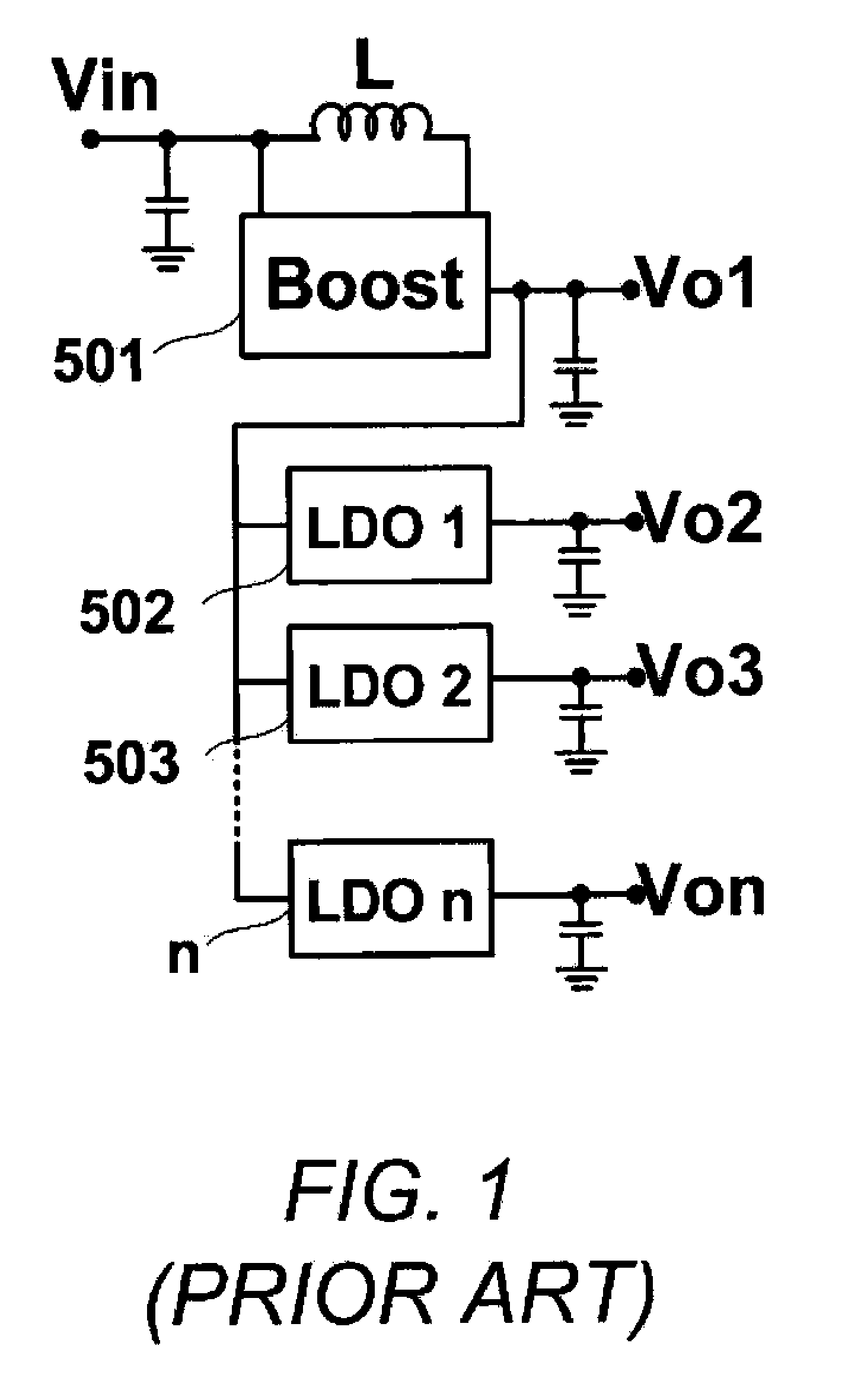
The loss over the power transistor becomes more serious when LDO output currents are increased in heavy loads.
An effort to improve the performance of LDOs using a power transistor with larger size for high output current faces with chip area consumption which is not favorable in IC designs.
That means, the freewheel switch Sf is turned on in any switching cycle at a determined level Idc, even the inductor current Idc is not zero, causing energy dissipation in the resistance of the inductor and the freewheel switch due to the none-zero inductor current during the freewheel time, The overall efficiency, therefore, is badly influenced, especially when the number of outputs increases.
It is clear that implementation of n compensation networks will be really bulky.

Method used


Image

  • Multiple-Output DC-DC Converter
  • Multiple-Output DC-DC Converter
  • Multiple-Output DC-DC Converter

Examples


Embodiment Construction

[0024]From now, the description disclosed in this invention will only be about a 4-output converter. The number 4 of outputs is chosen to imply the characteristic of multiple outputs. However, it is clear that the scope of this invention is not limited to 4-output converters. The number of output can be any integer of two or more, but a converter is still in the range of this invention if it uses the same control method of comparator(s) and one error amplifier.

[0025]A DC / DC switching power supply, which can power four positive outputs, includes one inductor 105, three comparators 161, 162, 163, and one error amplifier (EA) 164 in feedback loops, one control circuit, one inductor and six power switches (four output switches 141, 142, 143, 144; one main shared switch 140 and one freewheel switch 145). The three comparators 161, 162, and 163 are put in the feedback loops of the first three outputs to sense their voltage levels. The error amplifier 164, which is, usually but not limited...


PUM


Abstract

The invention relates to a DC / DC converter design. The converter requires only one single inductor to draw energy from one input source and distribute it to more than one outputs, employing Flexible-Order Power-Distributive Control (FOPDC). It include a single inductor, a number of power switches, comparators, only one error amplifier, a detecting circuit and a control block to regulate outputs. This converter can correctly regulate multiple outputs with fast transient response, low cross regulation, and effective switching frequency for each output. It can work in both discontinuous conduction mode (DCM) and continuous conduction mode (CCM). Moreover, with FOPDC, future output extension is simple, making a shorter time-to-market process for next versions of the converter. The design can be applied to different types of DC-DC converter.

Description

FIELD OF THE INVENTION[0001]The invention relates to DC-DC switching converters, and more specifically, to single-inductor multiple-output DC-DC converters.BACKGROUND OF THE INVENTION[0002]DC / DC switching converter is an indispensable part of many power management systems. As all designs are put into an effort of size reduction, converter cannot stay out of that trend. Designers, therefore, are exploring the way to shrink the size in both on-chip and off-chip implementation. Of all the approaches, Single-Inductor Multiple-Output (SIMO) converters come to prevail. With only one single inductor to regulate more than one output, the implementation can avoid problems that happen in conventional types of converters, such as too many bulky power devices as inductors, capacitors, and control ICs. Hence, the cost of mass-production is obviously much reduced. Single Inductor Multiple Output (SIMO) shows up as a most suitable and cost-effective solution in future development of DC-DC converte...

Claims


Application Information

Patent Timeline
IPC IPC(8): H02J1/00
CPCH02J1/08H02M2001/009H02M3/33561H02M3/158H02M1/009
Inventor CHO, GYUHALE, HANH PHUC
Owner JDA TECH
Learn More