
Barrier Fencing System

Inactive Publication Date: 2008-09-25
METAL FOUND ACQUISITION
View PDF56 Cites 16 Cited by
  • Summary
  • Abstract
  • Description
  • Claims
  • Application Information

AI Technical Summary

Benefits of technology

[0009]It is, therefore, one object of the present invention to provide a barrier fencing arrangement that overcomes some or all of the drawbacks and deficiencies of the prior art. It is another object of the present invention to provide a barrier fencing arrangement that is relatively simple in its installation and provides appropriate security against unauthorized persons from tunneling under and / or vehicles from driving through the border. It is a further object of the present invention to provide a barrier fencing arrangement that can be installed in a modular approach. It is a still further object of the present invention to provide a barrier fencing arrangement that can be installed with or integrated with existing structures and systems, e.g., foundational systems, anchoring devices, existing barriers, permanent vehicle barriers, etc. It is yet another object of the present invention to provide a barrier fencing arrangement that allows for effective installation regardless of location, terrain and accessibility. It is another object of the present invention to provide a barrier fencing arrangement that can meet some or all of the required performance criteria and provide for a cost effective and expedient installation method and process for securing borders and border areas, where appropriate.

Problems solved by technology

According to the prior art, and in connection with border security, current fence barrier systems being utilized involve a significant amount of components that require considerable time to put together during the installation process.
In addition, there are multiple steps involved to complete the installation process, and in many instances, such existing systems are unable to meet all of the United States Customs and Border Patrol performance criteria for the specified “Fence Barrier System”.
Further, current arrangements and methods being used are both costly and timely when trying to meet the required performance criteria given the location, terrain, and accessibility to the border in which the Fence Barrier System is needed.

Method used


Image

  • Barrier Fencing System
  • Barrier Fencing System
  • Barrier Fencing System

Examples


Embodiment Construction

[0033]For purposes of the description hereinafter, the terms “upper”, “lower”, “right”, “left”, “vertical”, “horizontal”, “top”, “bottom”, “lateral”, “longitudinal” and derivatives thereof shall relate to the invention as it is oriented in the drawing figures. However, it is to be understood that the invention may assume various alternative variations and step sequences, except where expressly specified to the contrary. It is also to be understood that the specific devices and processes illustrated in the attached drawings, and described in the following specification, are simply exemplary embodiments of the invention. Hence, specific dimensions and other physical characteristics related to the embodiments disclosed herein are not to be considered as limiting.

[0034]It is to be understood that the invention may assume various alternative variations and step sequences, except where expressly specified to the contrary. It is also to be understood that the specific devices and processes...


PUM


Abstract

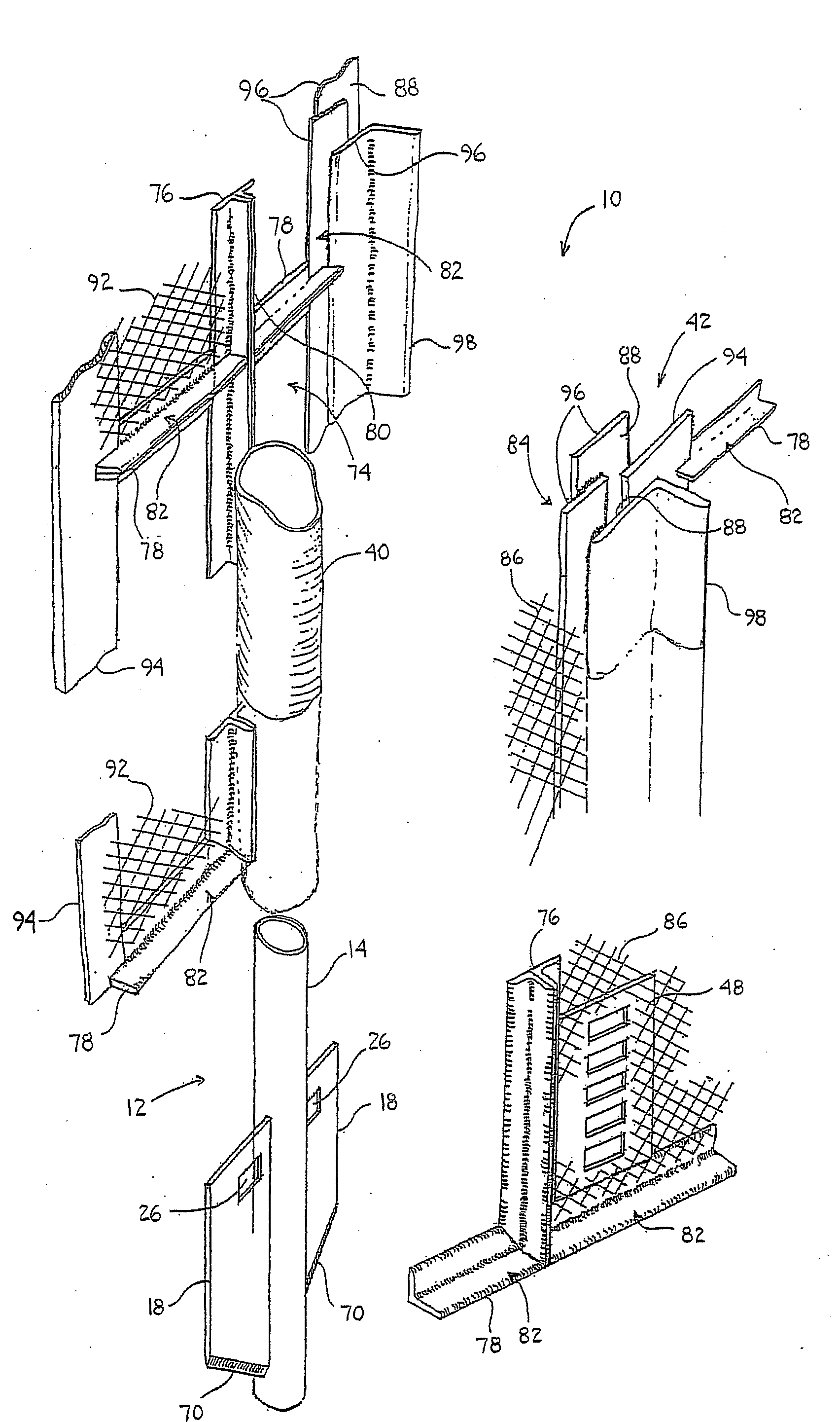
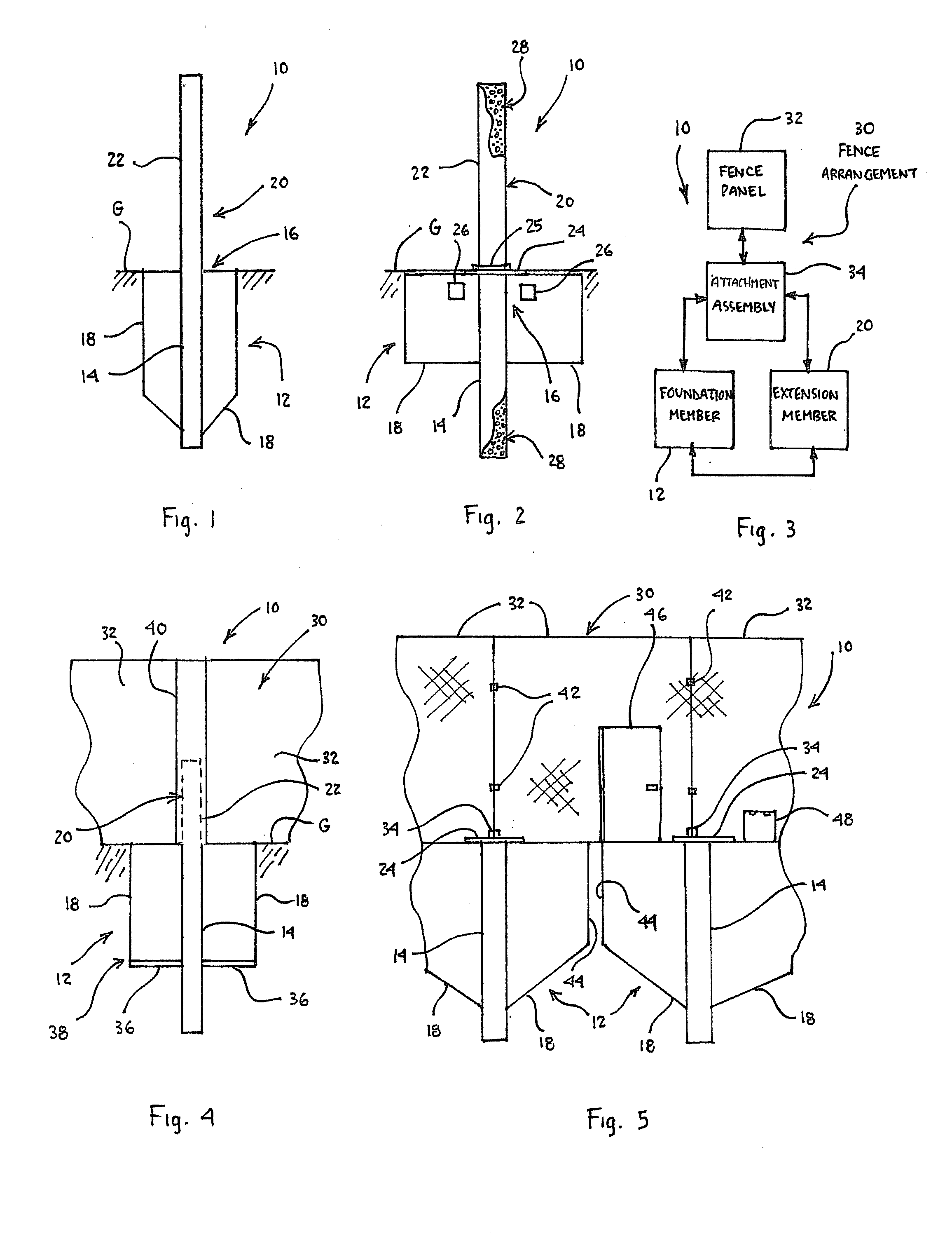
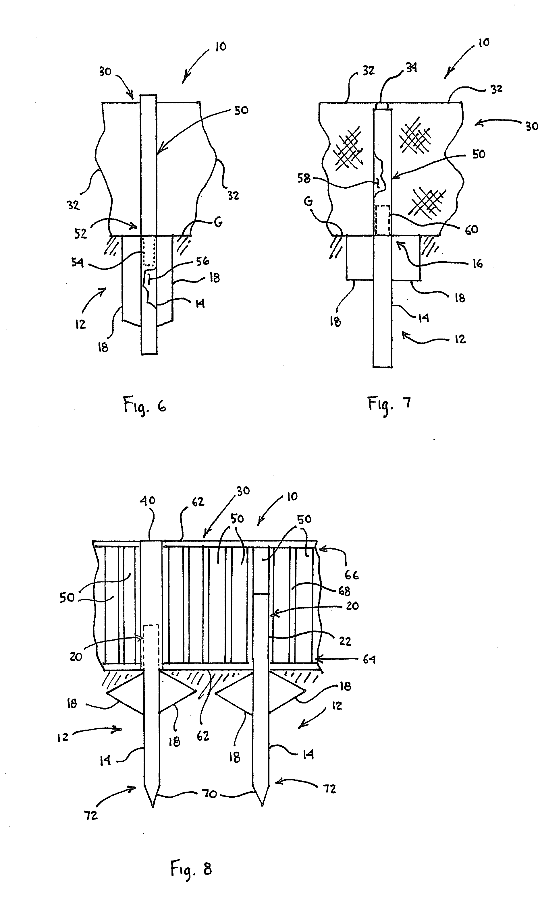
A barrier fencing arrangement, including a foundation member positioned at least partially below a ground surface, where the foundation member includes a body with a top portion and at least one fin extending from the body. An extension member, having a body attached to or integral with the body of the foundation member, extends from the top portion of the body of the foundation member at least partially above the ground surface.

Description

CROSS REFERENCE TO RELATED APPLICATIONS[0001]This application claims the benefit of priority to U.S. Provisional Patent Application No. 60 / 919,641, filed Mar. 23, 2007, which is incorporated herein by reference in its entirety.BACKGROUND OF THE INVENTION[0002]1. Field of the Invention[0003]The present invention relates general to fencing systems and similar barrier-type arrangements, and in particular, to a modular fencing system that can be used in connection with preexisting and new anchoring and foundation support systems and arrangements.[0004]2. Description of the Related Art[0005]In the field of security, e.g., border security, various devices and systems must be employed to successfully establish a safe and protected border between various countries and other entities. In order to establish this border, and according to the prior art, various fencing and other barrier systems are employed in an attempt to prevent unauthorized vehicles and persons from penetrating the border. ...

Claims


Application Information

Patent Timeline
IPC IPC(8): E04H17/00
CPCE04H17/16E04H12/2215E04H17/17
Inventor REINERT, GARY L.
Owner METAL FOUND ACQUISITION
Learn More