Oropharyngeal Airway Device

Inactive Publication Date: 2008-09-25
WESTERN SYDNEY LOCAL HEALTH DISTRICT
View PDF16 Cites 25 Cited by
  • Summary
  • Abstract
  • Description
  • Claims
  • Application Information

AI Technical Summary

Benefits of technology

[0022]Preferably, the distal end of the tube also includes a protuberance configured to locate the device by engagement in the vallecula between the epiglottis and the back of the tongue. In a preferred form, the leading edge of the first opening forms the locating protuberance. More preferably this leading edge is rounded or swollen to exaggerate the locating formation and / or minimise trauma during insertion.
[0033]Desirably, the periphery of all openings in at least the second portion of the tube will be similarly marked in contrast to the rest of the internal surface of the tube to make recognition of each location easier for the endoscopist.
[0035]In those embodiments where the tube portion is produced from a relatively soft, flexible resilient material, the means for providing rigidity in the mouthpiece can include a reinforcing insert or attachment of another more rigid material.

Problems solved by technology

In this regard the majority of devices commonly used for basic airway management, such as the “Guedel” airway, are not made long enough to reach beyond the base of the tongue, thereby often necessitating repeated manual intervention by the practioner in the form of manipulation of the patients head and chin to maintain a patient airway.
It should also be noted that these devices are not in anyway designed to facilitate fibreoptic intubation.
Furthermore, other oropharyngeal devices that are specifically designed to assist fibreoptic intubation such as the “Berman” airway have a generally ‘J’ shaped profile which does not match well with the natural internal profile of the passages in a patient extending from the mouth opening through the oropharynx.
This configuration makes it difficult to insert and accurately position these devices, as well as being unnecessarily uncomfortable for the patient.
There is also a tendency with these ‘J’ shaped devices to depress the tongue, which may further contribute to creating an obstruction at the airway outlet.
Furthermore, the inappropriate profile of these prior art devices means that the outlets of the devices may be directed at and into adjacent tissue rather than the internal body passages, which then makes it very difficult to accurately feed and guide an endoscope or the like through the device and beyond.
While there have been recent published developments relating to proposed adjustable telescopic oropharyngeal airway devices that have the capacity for extension of the outlet to the base of the tongue, these devices suffer from a number of inherent disadvantages.
For example, the two part sliding construction is expensive, complicated to make and potentially difficult to operate.
The telescopic arrangement also has the potential to create sealing problems around the mouthpiece.
Furthermore, it is not easy to determine when these devices have been located at the optimal position and there is an increased risk the device could end up directed into the oesophagus under inexperienced hands.
Also, the profile is again of a generally ‘J’ shaped form that is far from ideal.
Furthermore, none of these prior art devices readily facilitate fibreoptic intubation via the nose as is often desirable when, for example, the patient is unconscious and / or has suffered severe facial trauma, or when surgery in or around the mouth is contemplated.

Method used


Image

  • Oropharyngeal Airway Device
  • Oropharyngeal Airway Device
  • Oropharyngeal Airway Device

Examples


Embodiment Construction

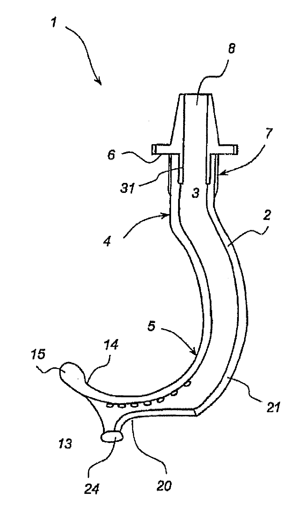
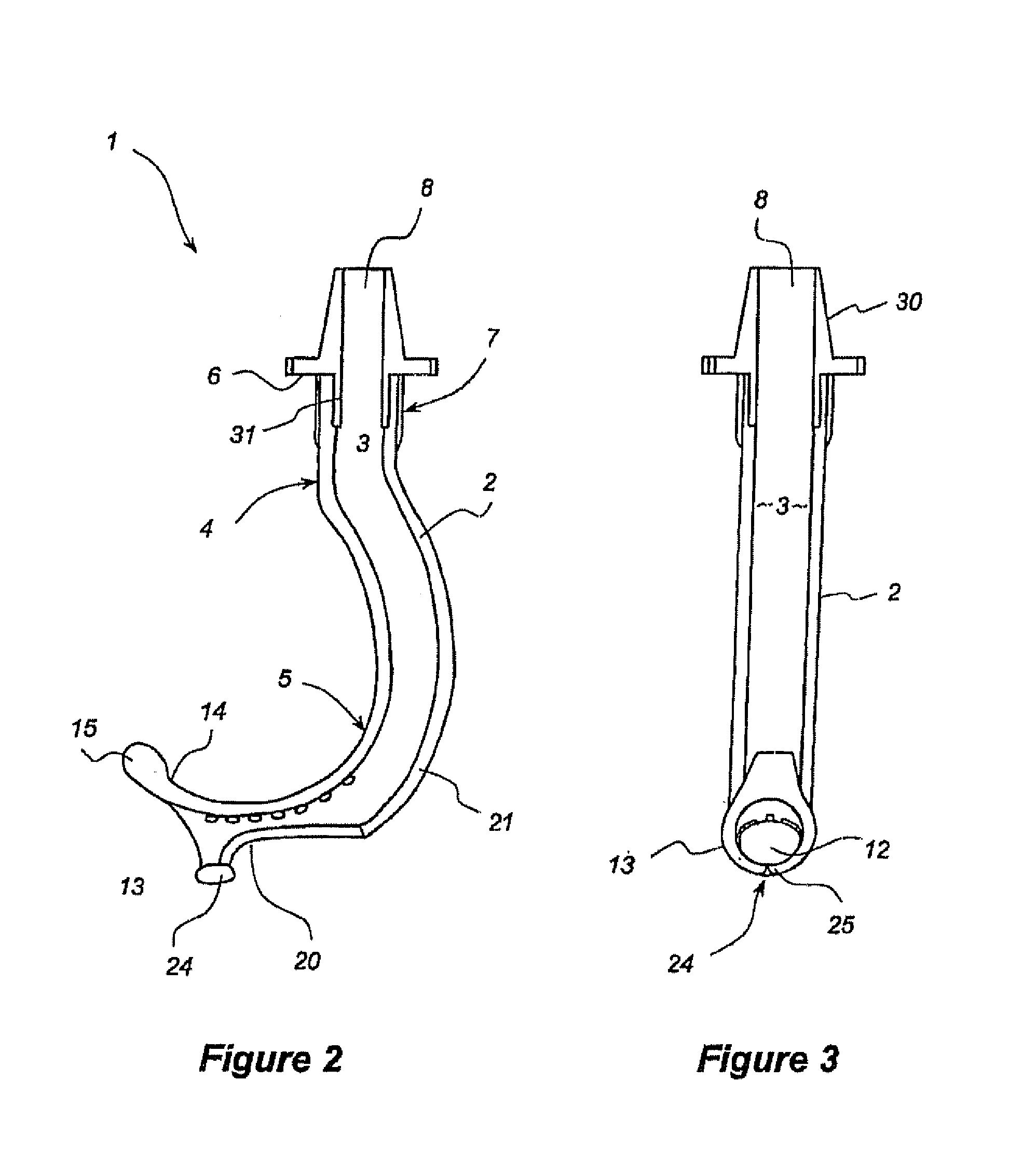
[0046]Referring to the drawings, there is shown an improved oropharyngeal airway device shown generally at 1. The device 1 includes a tube 2 having an open passage 3 extending therethrough.

[0047]The tube 2 comprises a first portion 4 and a second portion shown generally at 5. Connected to a proximal end of the first portion 4 is a flange 6 which in combination with the first portion 4 defines a mouthpiece shown generally at 7. The mouthpiece defines an inlet 8 to the passage 3.

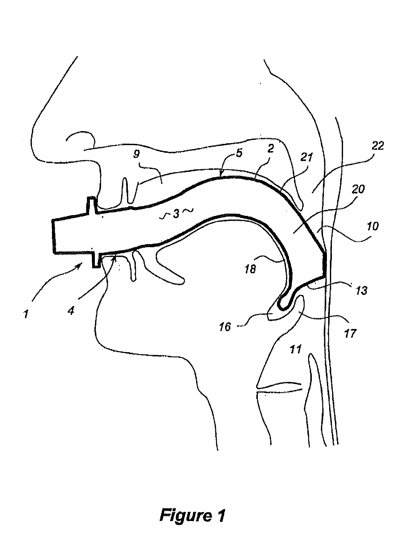
[0048]The tube 2 has a generally elliptical section and is longitudinally configured such that, in situ within a patient's mouth, it has a generally hook shaped profile (and is thus distinct from some prior art devices that have a generally ‘J’ shaped profile). In this case the first portion 4 of the tube 2 is generally straight and the second portion 5 has an arcuate form that extends obliquely from the first portion. This second arcuate portion 5 is configured to closely follow the pharyngeal arc defined by ...


PUM


Abstract

An oropharyngeal airway device (1) which includes a unitary tube (2) and a locating flange (6). The locating flange (6) forms, in combination with a first portion (4) of the tube (2), at least part of a mouthpiece (7) defining an inlet (8) to a passage (3). The flange (6) is adapted to locate adjacent an outer surface of the patient's mouth and the first portion (4) of the tube (2) extends into the mouth cavity. The tube (2) has a second portion (5), extending from said first portion (4), which has a distal end defining an outlet (12) to the tube (2) and which is adapted to extend to a location closely adjacent the base of the tongue. In use, the tube (2) is generally hook shaped with first portion (4) being substantially straight and the second portion (5) being of an arcuate form, extending obliquely from the first portion (4) and configured to follow the pharyngeal arc defined by the passage from the rear of the patient's mouth cavity through the oropharynx to a location adjacent the glottis. Alternatively or additionally to the tube shape described above, the outlet (12) at the distal end of the tube (2) can be defined by a first opening (13) that is configured to align with the opening to the larynx. Alternatively or additionally to the tube shape or the first opening described above, the device (1) can include internal markings (26) for guiding an endoscope therethrough.

Description

FIELD OF THE INVENTION[0001]The present invention relates to improvements in oropharyngeal airway devices. The improvements relate to the ease of effective use of such devices and to assisting fibreoptic intubation with the airways in place.[0002]A preferred form of the invention has been developed primarily for the purpose of facilitating nasal intubation and will be described in detail in relation to this particular use. However, it will be appreciated that the improved airway devices of the invention are also suited to use in basic airway management and for the more conventional procedure of intubation through the mouth.BACKGROUND OF THE INVENTION[0003]The design of oropharyngeal airways in common use has remained largely unchanged for many years and appears not to have taken into account recent advances in airway management. In this regard the majority of devices commonly used for basic airway management, such as the “Guedel” airway, are not made long enough to reach beyond the ...

Claims


Application Information

Patent Timeline
IPC IPC(8): A61M16/00A61B1/267A61M16/04
CPCA61B1/267A61M16/0495A61M16/0493A61M16/0488
Inventor PRINEAS, STEPHEN NICHOLAS
Owner WESTERN SYDNEY LOCAL HEALTH DISTRICT
Why Eureka
Try Eureka