
Suture Sleeve

a technology of suture sleeves and sleeves, applied in the field of suture sleeves, can solve the problems of difficult operation and complicated operation, and achieve the effect of facilitating the cutting of the tubular portion and reducing the risk of scalpel sliding

Inactive Publication Date: 2008-09-18
ST JUDE MEDICAL
View PDF0 Cites 37 Cited by
  • Summary
  • Abstract
  • Description
  • Claims
  • Application Information

AI Technical Summary

Benefits of technology

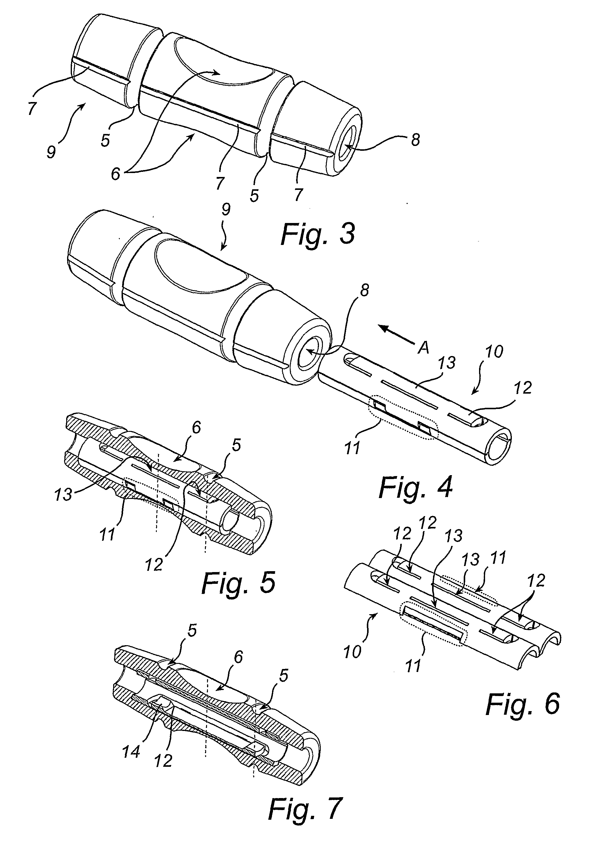
[0009]According to an aspect of the present invention, there is provided a suture sleeve for securing an implantable lead to body tissue, the implantable lead having an outer lead diameter, having a first tubular portion, having a lumen arranged for receiving said implantable lead. The first tubular portion has a locking arrangement for securing the suture sleeve at a position along the lead. The locking arrangement provides the suture sleeve with three modes of operation. In a first mode, the transversal size of the lumen exceeds the lead diameter, such that the suture sleeve is easily moveable along the lead. In a second mode, the transversal size of at least a portion of the lumen is reduced, whereby the first tubular portion applies a pressure onto the lead, such that the suture sleeve is prevented from moving along the lead. In a third mode, the pressure is temporarily released, such that the suture sleeve can be moved along the lead. A transition from the first mode to the second mode is provided by the locking arrangement in a first manner and a transition between the second mode and the third mode is provided by the locking arrangement in a second manner, which is different from the first manner.
[0033]Furthermore, the suture sleeve may be provided with a longitudinal slit, which is arranged to act as a cutting guide during removal of the suture sleeve from the lead. This will facilitate the cutting open of the tubular portion, if required, since the movement of a scalpel will be guided by the slit and the risk of the scalpel “sliding off” the tube and damaging surrounding tissue or the lead is reduced. This is particularly suitable in the embodiments with outer and inner tubular portions. Then, the longitudinal slit is provided on the outer surface of the outer tube, which preferably is made in a flexible material.

Problems solved by technology

In order for the lock member to release the lead to move freely within the sleeve, the lock member must be returned to the first position be pressing the opposite side of the lock member, which may be a delicate and difficult operation, especially when the sleeve and lead are positioned inside the body during implantation.

Method used


Image

  • Suture Sleeve
  • Suture Sleeve
  • Suture Sleeve

Examples


Embodiment Construction

[0045]The following is a description of exemplifying embodiments in accordance with the present invention. This description is intended for describing the general principles of the invention and is not to be taken in a limiting sense. Thus, even though a suture sleeve comprising separable outer and inner portions is illustrated, the scope of the invention includes suture sleeves constituted by one tubular portion. Furthermore, even though the illustrated locking arrangement comprises two means for performing the transitions between the three different modes of operation, a single means for performing the transitions, although in two different manners, is contemplated within the scope of the invention.

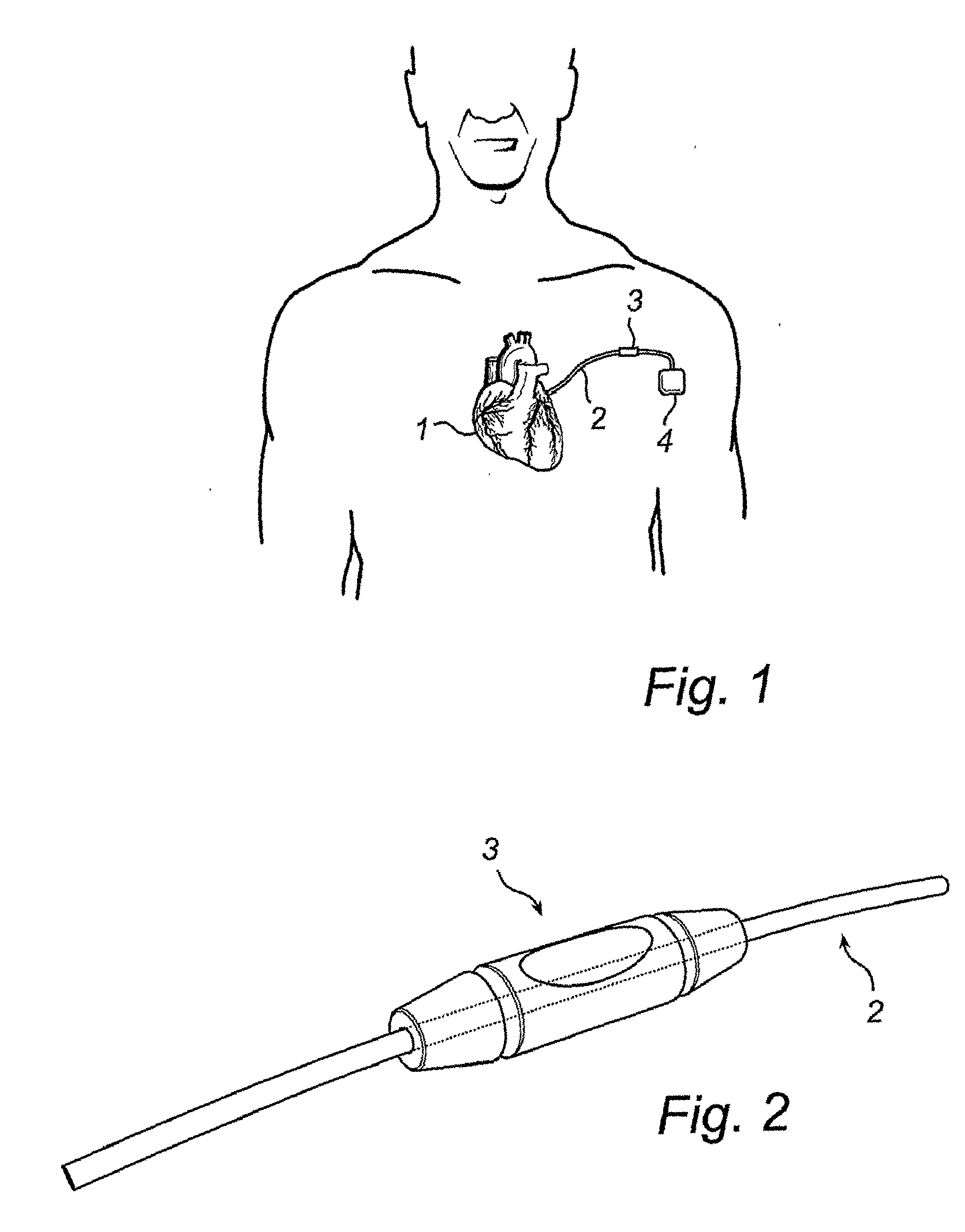
[0046]Referring first to FIG. 1, there is shown an implantable heart stimulator 4′ when implanted in a patient's body. A lead 2 connects the heart stimulator 4 to the heart 1, thereby allowing stimulation of the heart 1 and control of the heart rhythm. A suture sleeve 3 is provided at a...


PUM


Abstract

A suture sleeve for securing an implantable lead to body tissue has a lumen that receives the lead and that includes a locking arrangement that secures the sleeve at a selected position along the lead. The locking arrangement provides the suture sleeve with three modes of operation. In the first mode, the size of the lumen exceeds the diameter of the lead, such that the suture sleeve is easily movable along the lead. In the second mode, the size of at least a portion of the lumen is reduced, causing the sleeve to apply pressure to the lead so that relative movement between the sleeve and the lead is prevented. In the third mode, the pressure is temporarily released, allowing the sleeve to again be movable along the lead.

Description

BACKGROUND OF THE INVENTION[0001]1. Field of the Invention[0002]The present invention generally relates to the field of implantable medical devices. More specifically, the present invention relates to a suture sleeve for securing an implantable lead to body tissue.[0003]2. Description of the Prior Art[0004]Suture sleeves are used for securing a lead to a patient's body tissue, for instance a lead used for electrical connection between a heart stimulator, e.g. a pacemaker, and a heart. The purpose of the suture sleeve is to provide an aid for suturing and fixating the lead at a desired position in the body, which in the field of heart stimulators generally is at the point of entry into a vein. Thus, the suture sleeve is arranged to fixate the sleeve at a selected position along the lead, and often presents a guiding groove, or the like, into which the suture can be tied.[0005]U.S. Pat. No. 5,273,053 discloses a suture sleeve, which is adapted to secure a lead to a patient's body tiss...

Claims


Application Information

Patent Timeline
Patent Type & Authority Applications(United States)
IPC IPC(8): A61N1/05
CPCA61M5/1418A61M25/02A61M2025/024A61N2001/0582A61M2205/04A61N1/057A61M2025/028
Inventor HILL, ROLF
Owner ST JUDE MEDICAL
Learn More