
Systems and methods for filling occluded information for 2-d to 3-d conversion

a technology of filling and occluded information, applied in the field of two-dimensional (2d) to three-dimensional (3d) conversion of images, can solve the problems of distortion of the object being stretched, the fundamental problem of current conversion methods, and the need to completely reconstruct the 2-d image and video with 3-d information

Active Publication Date: 2008-09-18
INTELLECTUAL DISCOVERY CO LTD
View PDF35 Cites 69 Cited by
  • Summary
  • Abstract
  • Description
  • Claims
  • Application Information

AI Technical Summary

Benefits of technology

[0013]Embodiments of the invention are directed to systems and methods for processing 2-D to 3-D image conversion. Embodiments includes erode filling when an object has been removed from an image. In one embodiment, a target binary t image mask of the removed object is used for comparison with a binary source mask of the image. In an iterative proce...

Problems solved by technology

Unfortunately, most of the images and videos created today are 2-D in nature.
However, imbuing 2-D images and video with 3-D information often requires completely reconstructing the scene from the original 2-D data depicted.
Specifically, the stretching operations cause distortion of the object being stretched.
However, fundamental problems still exist with current conversion methods.
Nor can the known conversion methods take advantage of the processor saving aspects of other applications, such as robot navigation applications that, while having to operate in real time using verbose and poor quality images, can limit attention to specific areas of interest and have no need to synthesize image data for segmented objects.
In addition, existing methods of conversion are not ideally suited for scene reconstruction.
The reasons for this include excessive computational burden, inadequate facility for scene refinement, and the point clouds extracted from the images do not fully express model-specific geometry, such as lines and planes.
The excessive computational burden often arises because these methods correlate all of the extracted features across all frames used for the reconstruction in a single step.
Additionally, existing methods may not provide for adequate interactivity with a user that could leverage user knowledge of scene content for improving the reconstruction.
The existing techniques are also not well suited to the 2-D to 3-D conversion of things such as motion pictures.
Existing techniques typically cannot account for dynamic objects, they usually use point clouds as models which are not adequate for rendering, and they do not accommodate very large sets of input images.
These techniques also typically do not accommodate varying levels of detail in scene geometry, do not allow for additional geometric constraints on object or camera models, do not provide a means to exploit shared geometry between distinct scenes (e.g., same set, different props), and do not have interactive refinement of a scene model.

Method used


Image

  • Systems and methods for filling occluded information for 2-d to 3-d conversion
  • Systems and methods for filling occluded information for 2-d to 3-d conversion
  • Systems and methods for filling occluded information for 2-d to 3-d conversion

Examples


Embodiment Construction

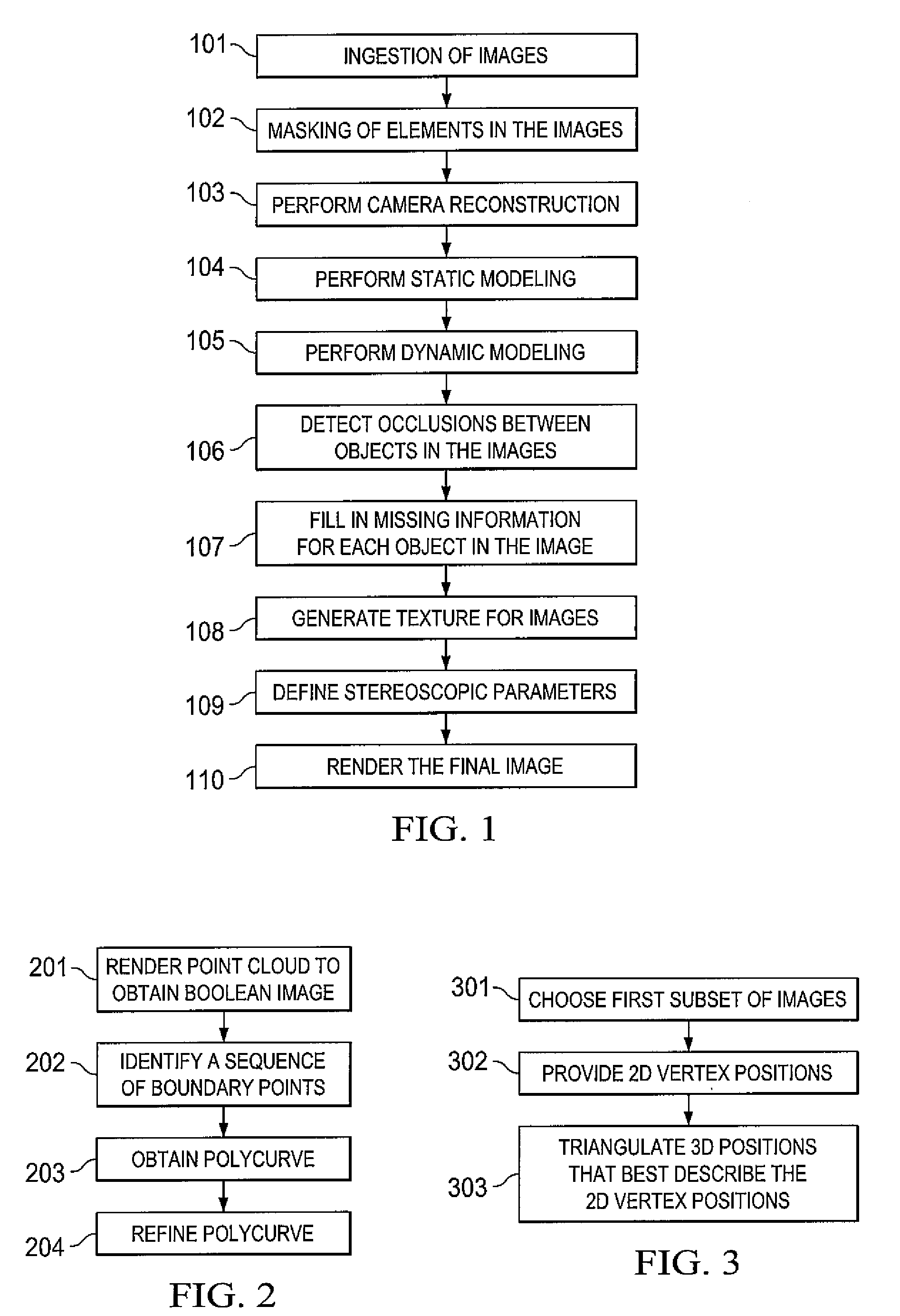
[0028]The process of converting a two dimensional (2-D) image to a three dimensional (3-D) image according to one embodiment of the invention can be broken down into several general steps. FIG. 1 is a flow diagram illustrating an example process of conversion at a general level. It should be noted that FIG. 1 presents a simplified approach to the process of conversions those skilled in the art will recognize that the steps illustrated can be modified in order such that steps can be performed concurrently. Additionally in some embodiments the order of steps is dependent upon each image. For example the step of masking can be performed, in some embodiments, up to the point that occlusion detection occurs. Furthermore, different embodiments may not perform every process shown in FIG. 1.

[0029]Additional description of some aspects of the processes discussed below can be found in, U.S. Pat. No. 6,456,745, issued Sep. 24, 2002, entitled METHOD AND APPARATUS FOR RE-SIZING AND ZOOMING IMAGE...


PUM


Abstract

The present invention is directed to systems and methods for processing 2-D to 3-D image conversion. The system and method includes erode filling when an object has been removed from an image. In one embodiment, a target binary t image mask of the removed object is used for comparison with a binary source mask of the image. In an iterative process, color differences between pixels in the target mask and pixels in the source mask are identified and the pixels in the target mask are changed working from the periphery of the target mask to the center of the mask. Color noise is eliminated in the filled region of the target mask and, if desired, random color noise is added to the filled target mask.

Description

CROSS-REFERENCE TO RELATED APPLICATIONS[0001]This application claims priority to U.S. Provisional Patent Application No. 60 / 894,450 filed Mar. 12, 2007 entitled “TWO-DIMENSIONAL TO THREE-DIMENSIONAL CONVERSION”, the disclosure of which is incorporated herein by reference and is also related to U.S. patent application Ser. No. (not yet issued) filed concurrently herewith, Attorney Docket No. 69126-P007U.S. Pat. No. 1,071,2471 entitled “SYSTEM AND METHOD FOR USING A MASK TO GENERATE A MODEL, OR A MODEL TO GENERATE A MASK, IN THE CONVERSION OF TWO-DIMENSIONAL IMAGES TO THREE-DIMENSIONAL IMAGES”; U.S. patent application Ser. No. (not yet issued) filed concurrently herewith, Attorney Docket No. 69126-P008US-10712472 entitled “SYSTEMS AND METHODS FOR 2-D TO 3-D CONVERSION USING DEPTH ACCESS SEGMENTS TO DEFINE AN OBJECT”; U.S. patent application Ser. No. (not yet issued) filed concurrently herewith, Attorney Docket No. 69126-P009U.S. Pat. No. 1,071,2473 entitled “SYSTEM AND METHOD FOR USIN...

Claims


Application Information

Patent Timeline
IPC IPC(8): G06K9/00
CPCG06T11/001G06T15/205G06T2207/10024G06T5/20G06T5/005G06T5/77
Inventor BIRTWISTLE, STEVENWALLNER, NATASCHAKEECH, GREGORY R.SIMMONS, CHRISTOPHER L.SPOONER, DAVID A.LOWE, DANNY D.
Owner INTELLECTUAL DISCOVERY CO LTD
Learn More