
Multifunctional lighting system

a multi-functional, lighting technology, applied in the direction of lighting and heating equipment, semiconductor devices for light sources, instruments, etc., can solve the problems of inefficient incandescent light bulbs used in households and businesses, rising energy costs, and not being integrated into incandescent bulbs

Inactive Publication Date: 2008-09-18
M I D ENTERPRISES
View PDF33 Cites 67 Cited by
  • Summary
  • Abstract
  • Description
  • Claims
  • Application Information

AI Technical Summary

Benefits of technology

[0016]In some embodiments, the system can include an instruction module embodied in a computer readable medium that is programmed to activate the camera upon activation of the sensor. In some embodiments, the sensor and camera are not apparent to a passerby, allowing the system to function as a hidden security or surveillance system. In some embodiments, the system includes an interface disposed within the housing, allowing the camera to send images to a remote computer. In some embodiments, the sensor can be coupled to an audible alarm for generating an audible tone after activation of the sensor. In some embodiments, the system can include a back-up power source.

Problems solved by technology

For years, inefficient incandescent light bulbs have been used throughout households and businesses.
Furthermore, rising energy costs and awareness of environmental hazard concerns are pushing governments, consumers, and businesses to look at innovative ways to reduce electrical consumption.
Motion switches and sensors, for example, are known to save energy but have not been integrated into incandescent bulbs for a variety of reasons.
Such reasons include the problems associated with the generation of extreme heat during the use of traditional systems.
The substantial heat results in rapid failure of the components or the inability to incorporate certain components.
As a result, the functionality contemplated for integration around the light bulb has not been effectively addressed.
For at least these reasons, traditional lighting sources have not been designed to incorporate circuitry and solid state electronics, such as motion switches and sensors, into the lighting unit itself, resulting in a single unit, self-contained system.

Method used


Image

  • Multifunctional lighting system
  • Multifunctional lighting system
  • Multifunctional lighting system

Examples


Embodiment Construction

[0021]One of skill will appreciate that the teachings provided herein are generally directed to a single unit, energy efficient, lighting and safety system, and that several uses are possible for such a system, and these uses are not limited to the uses discussed above. One use for a single unit, energy efficient, lighting and safety system can be similar to the use for a motion activated light fixture that is currently on the market.

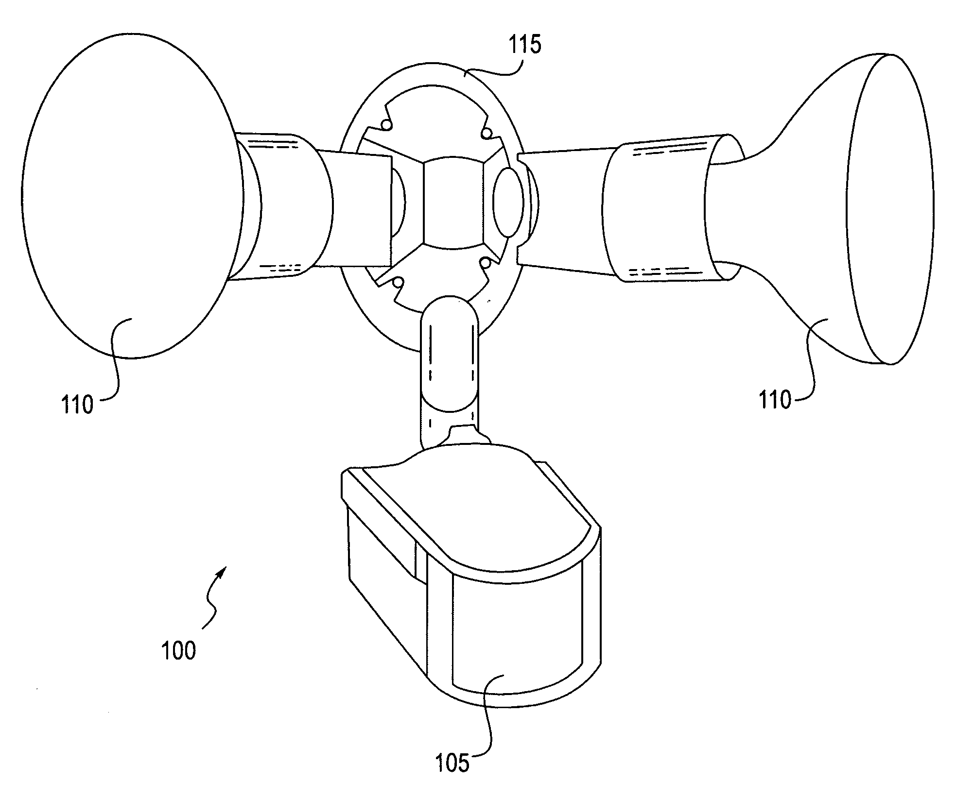
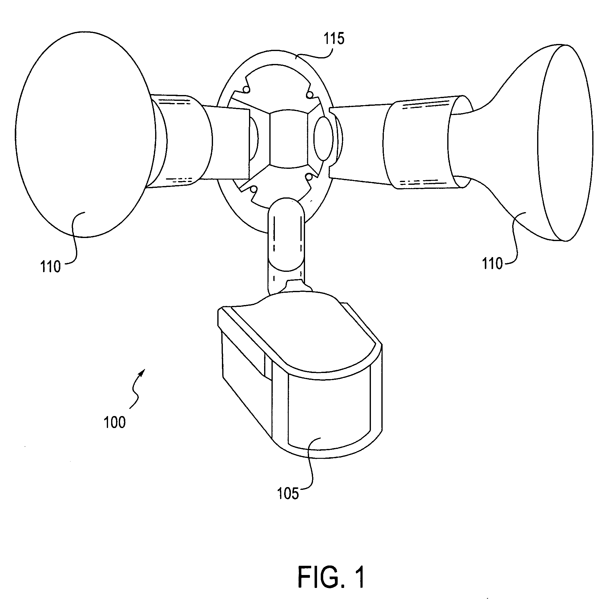
[0022]As described above, current light fixtures have much room for improvement. FIG. 1 illustrates a motion activated light fixture that is currently on the market. The light fixture 100 has a protruding external sensor 105 mounted between the two light bulbs 110. The sensor 105 is adjustable in position so that it can be aimed in various directions to detect motion when the fixture is mounted on the eaves or ceiling or on a wall. This current configuration of the light fixture 100 requires space considerations, and a modification to accommodate mounti...


PUM


Abstract

The teachings herein generally relate to a single unit, energy efficient, lighting and safety system and a security surveillance system that includes the lighting and safety system. The lighting and safety system that includes an enclosed housing having a lens, a fitting configured to connect to a standard receptacle, and a sensor that can be activated upon detection of sound, heat, or motion; an illumination source disposed within the housing and creating a maximum temperature of less than 70° C. in the atmosphere that is in contact with the illumination source; and a current control engine that is disposed within the housing and coupled to the sensor and illumination source to control current to the illumination source upon activation of the sensor.

Description

CROSS-REFERENCE TO RELATED APPLICATIONS[0001]This application claims the benefit of U.S. Provisional Application No. 60 / 918,626 filed Mar. 15, 2007, which is hereby incorporated herein by reference in its entirety.BACKGROUND[0002]1. Field of the Invention[0003]The teachings herein generally relate to a single unit, energy efficient, lighting and safety system, and a security surveillance system that includes the lighting and safety system.[0004]2. Description of the Related Art[0005]For years, inefficient incandescent light bulbs have been used throughout households and businesses. Furthermore, rising energy costs and awareness of environmental hazard concerns are pushing governments, consumers, and businesses to look at innovative ways to reduce electrical consumption.[0006]Many states are coming up with mandates and recommendations to save energy costs in both governmental and private buildings. Motion switches and sensors, for example, are known to save energy but have not been i...

Claims


Application Information

Patent Timeline
Patent Type & Authority Applications(United States)
IPC IPC(8): G08B19/00
CPCF21V23/0442F21V33/0076F21W2131/10F21Y2101/02G08B13/19695F21K9/13H05B33/0803H05B33/0869H05B37/0227Y02B20/383Y02B20/44G08B15/001F21K9/23F21Y2115/10H05B45/22H05B45/30H05B47/105Y02B20/30Y02B20/40
Inventor SIRHAN, GENO
Owner M I D ENTERPRISES
Learn More