
Wheel suspension

a technology of suspension and wheel, applied in the direction of resilient suspension, vibration damper, mechanical apparatus, etc., can solve the problems of geometric or spatially complex springs, deflection and rebound of jerking springs, and unavoidable relative movements, so as to achieve less negative effect and less relative movement

Inactive Publication Date: 2008-09-18
MUHR UND BENNDER KG
View PDF0 Cites 7 Cited by
  • Summary
  • Abstract
  • Description
  • Claims
  • Application Information

AI Technical Summary

Benefits of technology

[0013]Thus, the object of the invention is to improve the known wheel suspension in such a manner that the undesired, but unavoidable relative movement between the lower spring end of the helical compression spring and the lower spring plate connected to the shock absorber have a less negative effect than the prior art and / or that less relative movement occurs that in the prior art.
[0018]As described above, the object of the invention is to improve the wheel suspension in such a manner that the undesired, but unavoidable relative movement between the lower spring end of the helical compression spring and the lower spring plate connected to the shock absorber have a less negative effect than the prior art and / or that there is less relative movement in the type under consideration. The first part of this object is met with what has previously been described, in other words that a particular undesired, but unavoidable relative movement between the lower spring end of the helical compression spring and the lower spring plate connected to the shock absorber is accepted and the damaging effects of exactly this relative movement are reduced or, respectively even entirely eliminated.

Problems solved by technology

That gives rise to considerable frictional forces on the piston of the shock absorber and consequently leads to a jerking spring deflection or rebound.
These relative movements are unavoidable because, on the one hand, the deflection and rebound of the helical compression spring, is, by all means a complicated structure and because, however, on the other hand, particularly the system of the helical compression spring as well as of the upper spring plate and the lower spring plate is geometrically or, respectively, spatially complicated in terms of deflection and rebound.
This is generally not desired in the upper spring plate connected to the body, but more of a result of unavoidable tolerances; however, in the lower spring place connected to the shock absorber desirable in order to eliminate or, respectively reduce transverse forces that would otherwise occur.
Since, as described, the upper offset is relatively small, but the lower offset is relatively large, disadvantages arise with the undesired, but unavoidable relative movement; particularly on the lower spring end of the helical compression spring or, respectively, on the lower spring plate connected to the shock absorber.
Nevertheless, damages occur to the coating of the helical compression spring where the described undesired, but unavoidable relative movement between the lower spring end of the helical compression spring and the lower spring plate connected to the shock absorber, for example chafing particles entering into this area and through occurring corrosion, in particular through corrosion that is, in turn, the result of chafing particles.
In the end, spring fractures occur again and again in the area of the lower spring end of the helical compression spring, so that the helical compression springs have to be oversized in order to avoid such spring fractures or, respectively, the material used cannot be optimally taken advantage of.

Method used


Image

  • Wheel suspension
  • Wheel suspension
  • Wheel suspension

Examples


Embodiment Construction

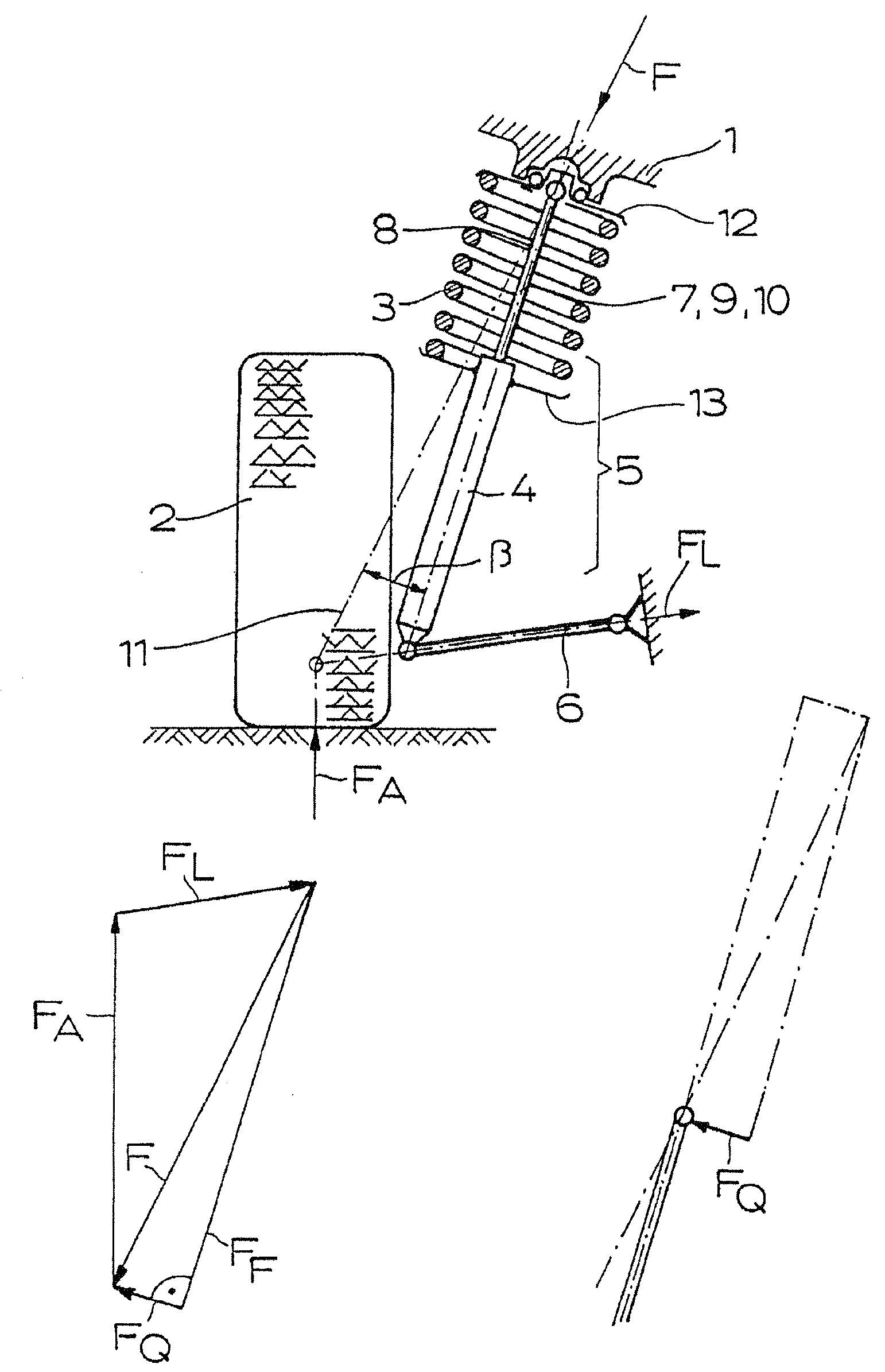
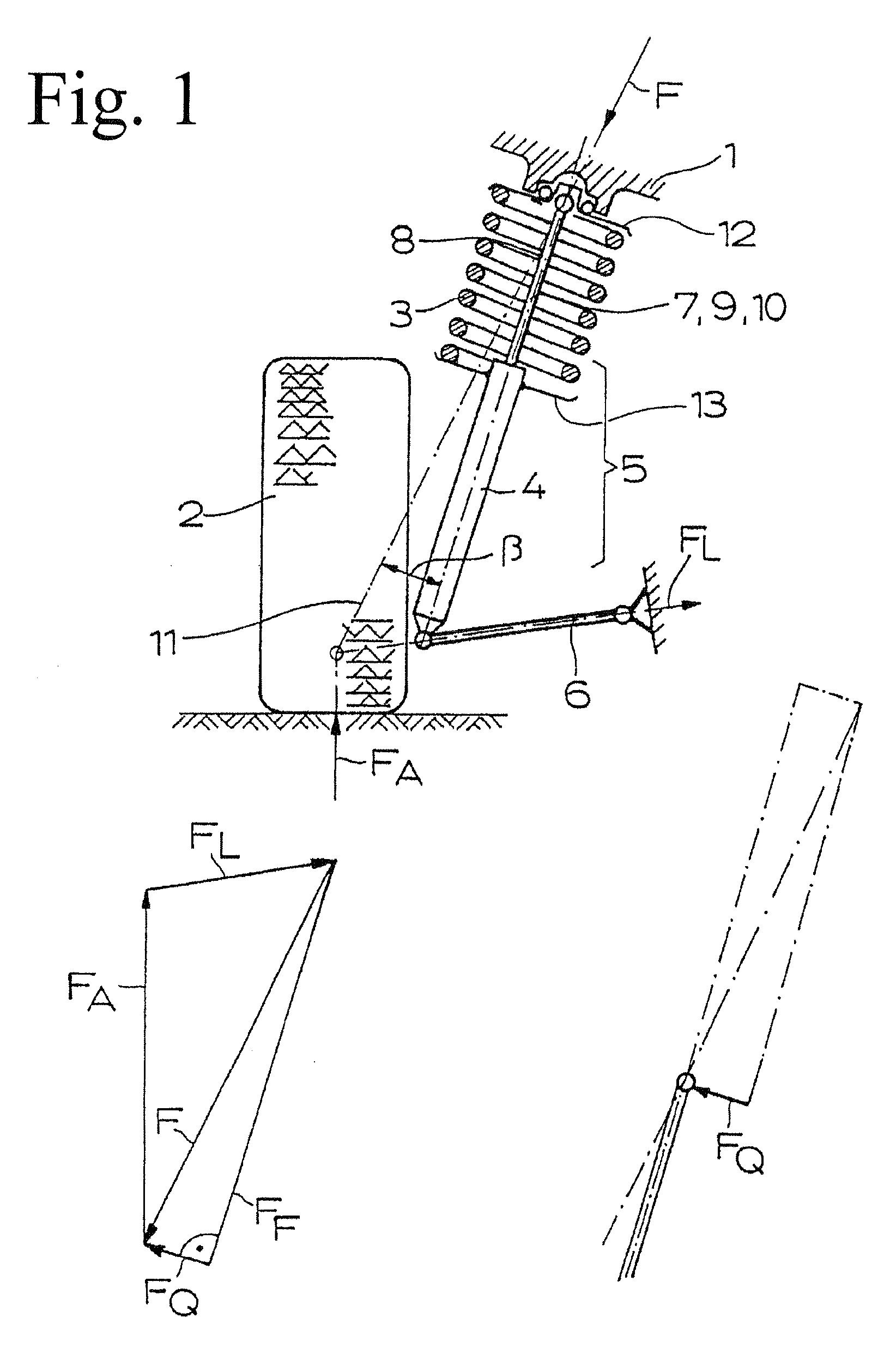
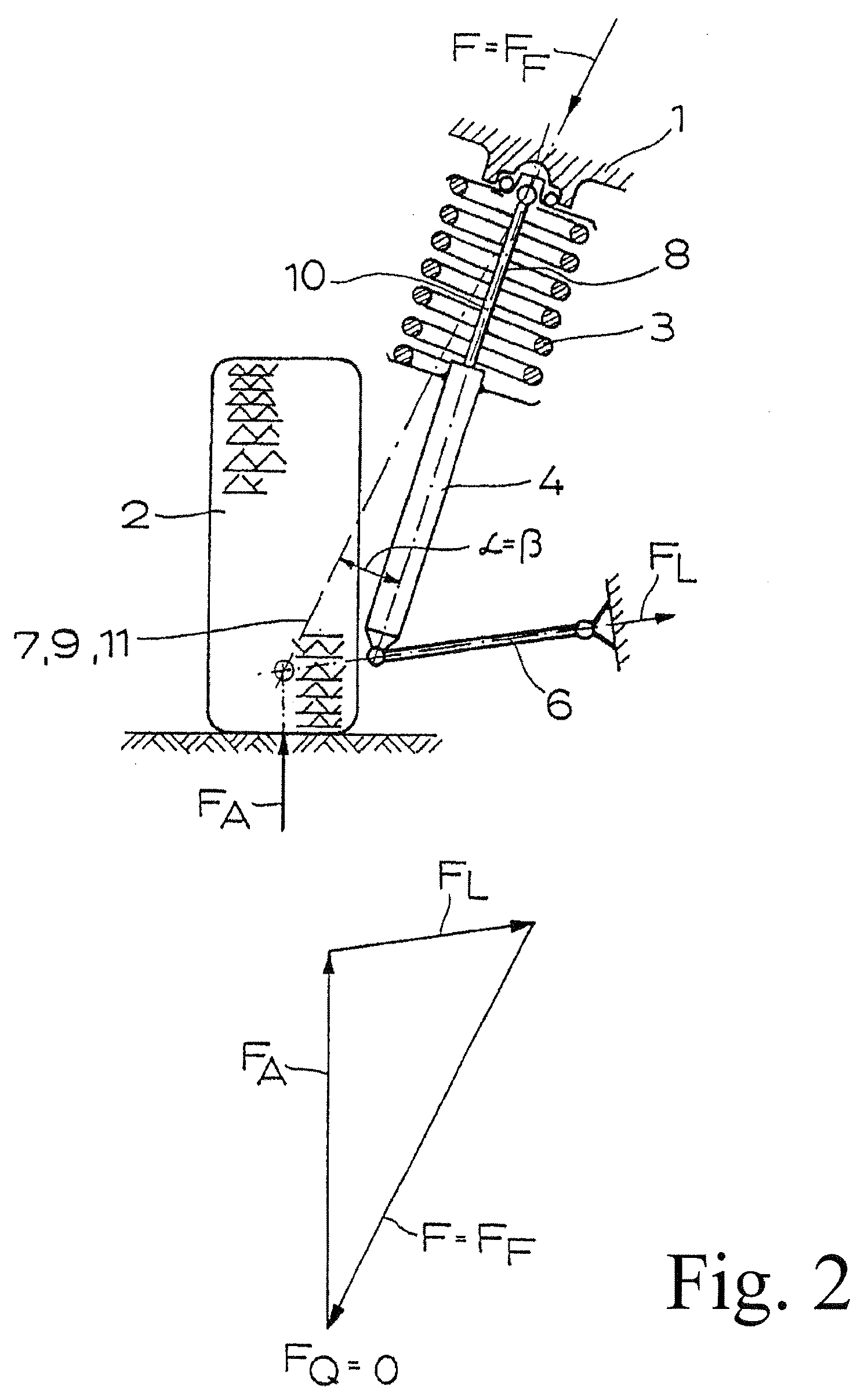
[0032]A wheel-guiding McPherson strut unit 5 having a helical compression spring 3 (=suspension spring or, respectively, axle spring) and a shock absorber 4, and being connected to the body 1 and to the wheel 2 as well as a suspension arm 6 belong to the wheel suspension represented in FIGS. 1 and 2. The spring center line 7 of the helical compression spring 3 is also depicted. That spring center lines are not physically existent and how spring center lines are determined in helical compression springs is referred to in the corresponding embodiment in the not yet published German Patent Application 10 2006 060 149.1.

[0033]As can be taken from FIG. 1, a force equilibrium is established between the different forces, specifically between the wheel contact force FA, the arm force FL, the body support force F, the spring force FF and the transverse force FQ. The unwanted transverse force FQ, which leads to friction forces on the piston of the shock absorber 4 and which is to be accommoda...


PUM


Abstract

A wheel suspension has a wheel-guiding McPherson strut unit which includes a helical compression spring and a shock absorber, and which is connected to a vehicle body, on the one hand, and to a wheel on the other, and with a suspension arm wherein the compression spring is provided between an upper spring plate connected to the body and a lower spring plate connected to the shock absorber. The undesired, but unavoidable relative movements between the lower spring end of the compression spring and the lower spring plate connected to the shock absorber have an effect that is less negative than usual due to a coating provided between the lower spring end of the helical compression spring and the lower spring plate connected to the shock absorber protecting the lower spring end of the helical compression spring and / or the lower spring plate connected to the shock absorber.

Description

BACKGROUND OF THE INVENTION[0001]The invention relates to a wheel suspension with a wheel-guiding McPherson strut unit which has a helical compression spring and a shock absorber, and which is connected to the vehicle body, on the one hand, and to the wheel on the other, and with a suspension arm wherein the helical compression spring is provided between an upper spring plate connected to the body and a lower spring plate connected to the shock absorber. The parts previously designated as upper spring plate and lower spring plate are also often designated as spring plate.[0002]In wheel suspensions of the type basically under consideration here, also often called McPherson strut wheel suspensions, the upper suspension arm, which is pre-sent in other conventional wheel suspensions, is replaced by a long-stroke McPherson strut unit (Lueger “Lexicon der Technik”, Volume 12“Lexikon der Fahrzeugtechnik”, 1967 Deutsche Verlags-Anstalt GmbH, p. 425).[0003]In the present wheel suspensions tr...

Claims


Application Information

Patent Timeline
IPC IPC(8): F16F13/00
CPCB60G15/063B60G2204/1242B60G15/07
Inventor BRAND, ROBERTNEUBRANDT, JORGKRIESE, HANS-ULRICH
Owner MUHR UND BENNDER KG
Learn More