
Method for integrating event-related information and trace information

a trace information and event-related technology, applied in the field of emulation and debugging methods of microcontrollers, can solve the problems of difficult and sometimes virtually impossible for logic analyzers or oscilloscopes to have access to internal devices, and device under test may not be configured to output certain of its internal information to an external devi

Inactive Publication Date: 2008-09-11
CYPRESS SEMICON CORP
View PDF13 Cites 12 Cited by
  • Summary
  • Abstract
  • Description
  • Claims
  • Application Information

AI Technical Summary

Benefits of technology

The present invention provides a method for emulating and debugging devices such as microcontrollers without the need for expensive and specialized equipment like logic analyzers and oscilloscopes. The method uses an event thread executed on an emulator that operates in lock-step with the microcontroller. The event information is sampled and recorded as waveforms, which can be displayed and analyzed. The method also allows access to information that is difficult or impossible to access with conventional tools. The invention is useful for configurable microcontrollers and can monitor and display internal information without burdening the system. Overall, the invention simplifies the process of debugging and emulating devices and reduces the likelihood of errors.

Problems solved by technology

Logic analyzers in particular are relatively expensive pieces of equipment.
In addition, it is often difficult and sometimes virtually impossible for a logic analyzer or oscilloscope to have access to points (e.g., registers) and information internal to the device under test (e.g., the microcontroller).
For example, the device under test may not be configured to output certain of its internal information to an external device such as an oscilloscope or logic analyzer.
The act of filtering out the information of interest is burdensome and prone to error.
Another problem with the latter approach is that essentially the entire event and trace information is collected before the designer can filter out the information that is not of interest.
The amount of event and trace information may be substantial and so may consume a significant portion of available memory resources.
Conversely, if not enough memory is available, information may be lost.

Method used


Image

  • Method for integrating event-related information and trace information
  • Method for integrating event-related information and trace information
  • Method for integrating event-related information and trace information

Examples


Embodiment Construction

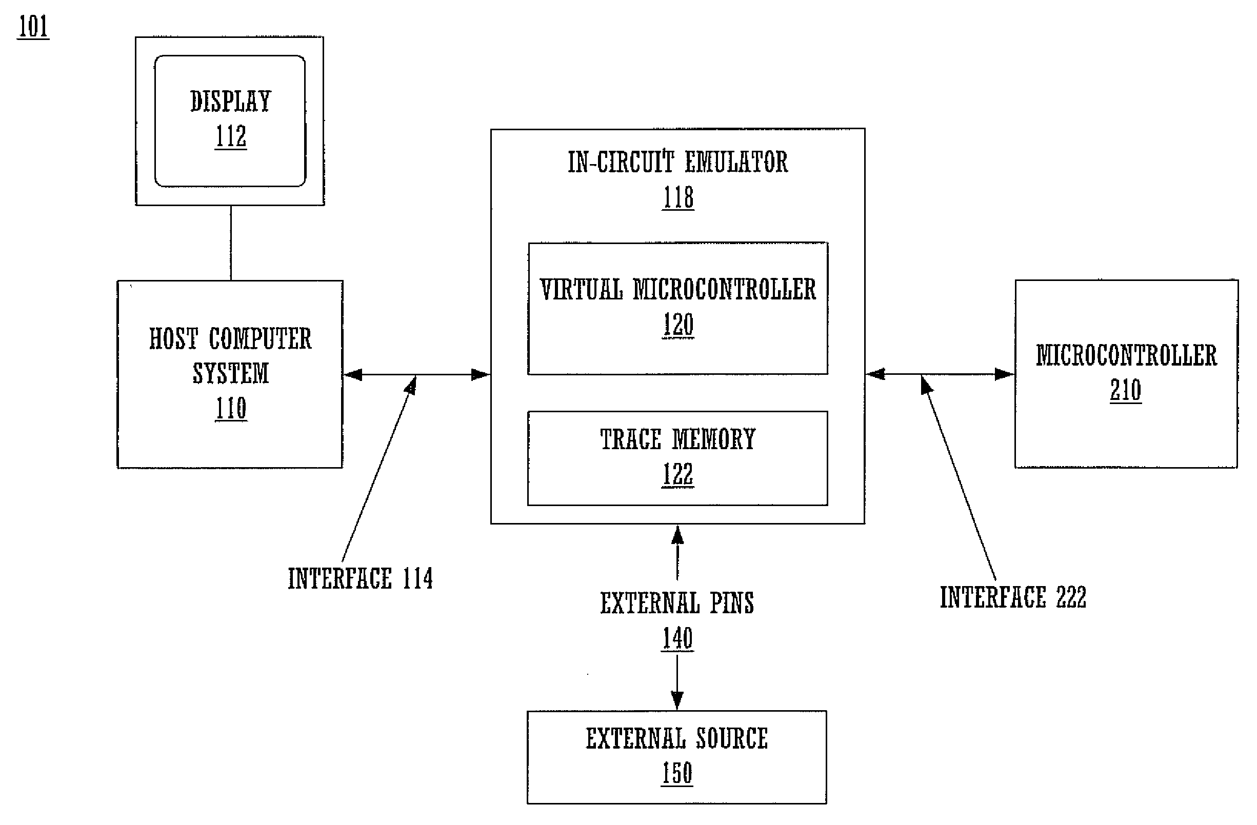
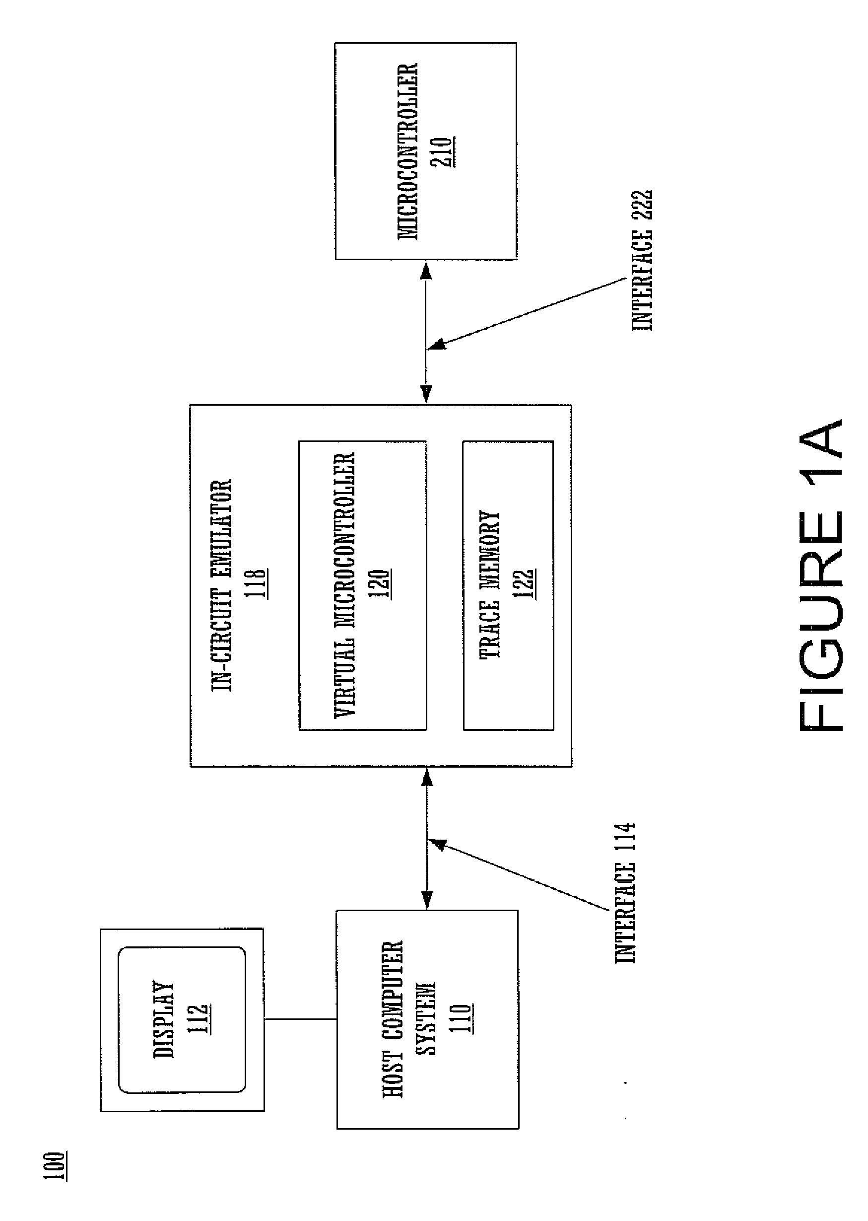
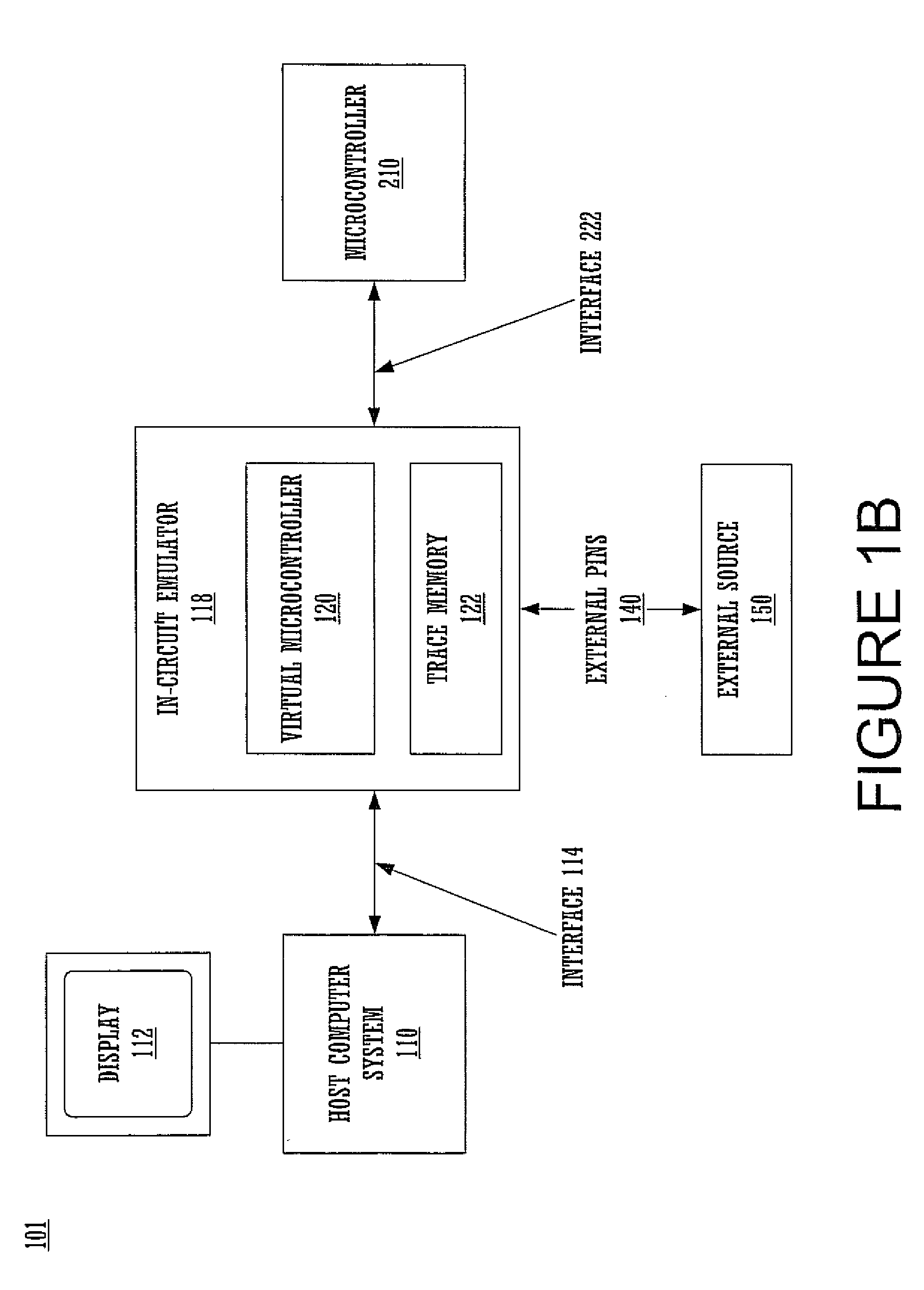
[0025]Reference will now be made in detail to the preferred embodiments of the invention, examples of which are illustrated in the accompanying drawings. While the invention will be described in conjunction with the preferred embodiments, it will be understood that they are not intended to limit the invention to these embodiments. On the contrary, the invention is intended to cover alternatives, modifications and equivalents, which may be included within the spirit and scope of the invention as defined by the appended claims. Furthermore, in the following detailed description of the present invention, numerous specific details are set forth in order to provide a thorough understanding of the present invention. However, it will be obvious to one of ordinary skill in the art that the present invention may be practiced without these specific details. In other instances, well-known methods, procedures, components, and circuits have not been described in detail so as not to unnecessarily...


PUM


Abstract

A method for emulating and debugging a microcontroller. In one embodiment, an event thread is executed on an emulator that operates in lock-step with the microcontroller. Event information is sampled at selected points. Trace information is also recorded at the selected points. As such, the event information and trace information are effectively pre-filtered. Accordingly, it is not incumbent on a designer to read and understand the event and trace information and sort out the information that is of interest. Instead, this task is essentially done automatically, helping the designer and reducing the probability of error. Furthermore, because only selected event and trace information is recorded, the resources of the in-circuit emulator system are not taxed.

Description

FIELD OF THE INVENTION[0001]Embodiments of the present invention relate to the field of in-circuit emulation. More specifically, embodiments of the present invention relate to an emulation and debugging method for a microcontroller.BACKGROUND ART[0002]In-circuit emulators have been used for a number of years by software and hardware developers to help diagnose and debug hardware and software. In-circuit emulation is commonly used to analyze and debug the behavior of complex devices such as microcontrollers and microprocessors that have internal structures too complex to be modeled using simulation software.[0003]A typical arrangement for in-circuit emulation includes a host computer system that is coupled to the microcontroller to be tested through some type of debug logic block. Instructions from the host computer system are loaded to the microcontroller through the debug logic block, which monitors the performance of the microcontroller as the instructions are executed by the micr...

Claims


Application Information

Patent Timeline
Patent Type & Authority Applications(United States)
IPC IPC(8): G06F11/00
CPCG06F11/3636
Inventor BARTZ, MANFREDNEMECEK, CRAIGPLEIS, MATT
Owner CYPRESS SEMICON CORP
Learn More