Eureka AIR delivers breakthrough ideas for toughest innovation challenges, trusted by R&D personnel around the world.

Unusable block management within a non-volatile memory system

a non-volatile memory system and management technology, applied in the direction of fault response, instruments, error detection/correction, etc., can solve problems such as defective blocks, failure to hold electrical charges, manufacturing or factory defects

Active Publication Date: 2007-01-30
SANDISK TECH LLC
View PDF25 Cites 108 Cited by
  • Summary
  • Abstract
  • Description
  • Claims
  • Application Information

AI Technical Summary

Benefits of technology

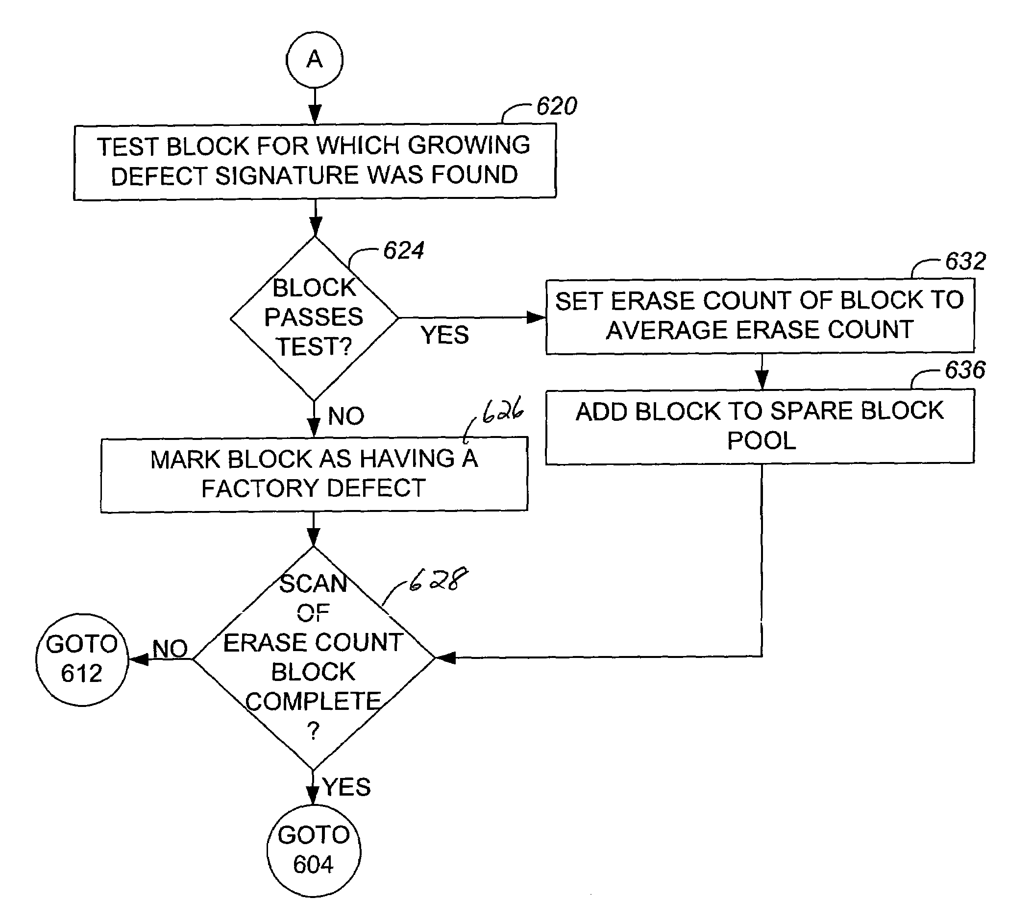
[0018]The ability to reclaim potentially usable blocks which have previously been identified as being unusable for use effectively enables substantially every available block within a non-volatile memory system to be used to store data, thereby enabling the memory system to be used and, hence, operate more efficiently. In one embodiment, blocks with growing defects, such as the inability to be successfully erased, which were once “good” but have become “bad,” may potentially be reclaimed after rigorous testing. By enabling some blocks to be reclaimed, the resources of a memory system may be used more efficiently.
[0020]In accordance with still another aspect of the present invention, a method for managing blocks within a non-volatile memory system includes determining when a first physical block within a non-volatile memory of the non-volatile memory system has a factory defect, storing a first signature in a data structure associated with the non-volatile memory which identifies the first physical block as having the factory defect when it is determined that the first physical block has the factory defect. The method also includes substantially preventing the first physical block from being used to store information when it is determined that the first physical block has the factory defect, determining when a second physical block within the non-volatile memory has a growing defect and storing a second signature in the data structure which identifies the second physical block as having the growing defect when it is determined that the second physical block has the growing defect. Finally, the method includes substantially preventing the second physical block from being used to store information when it is determined that the first physical block has the growing defect.

Problems solved by technology

When a flash memory is manufactured, manufacturing or factory defects are typically identified by the manufacturer of the flash memory.
The defective blocks may, for example, fail to hold electrical charges and fail stress tests applied by the manufacturer of the flash memory.
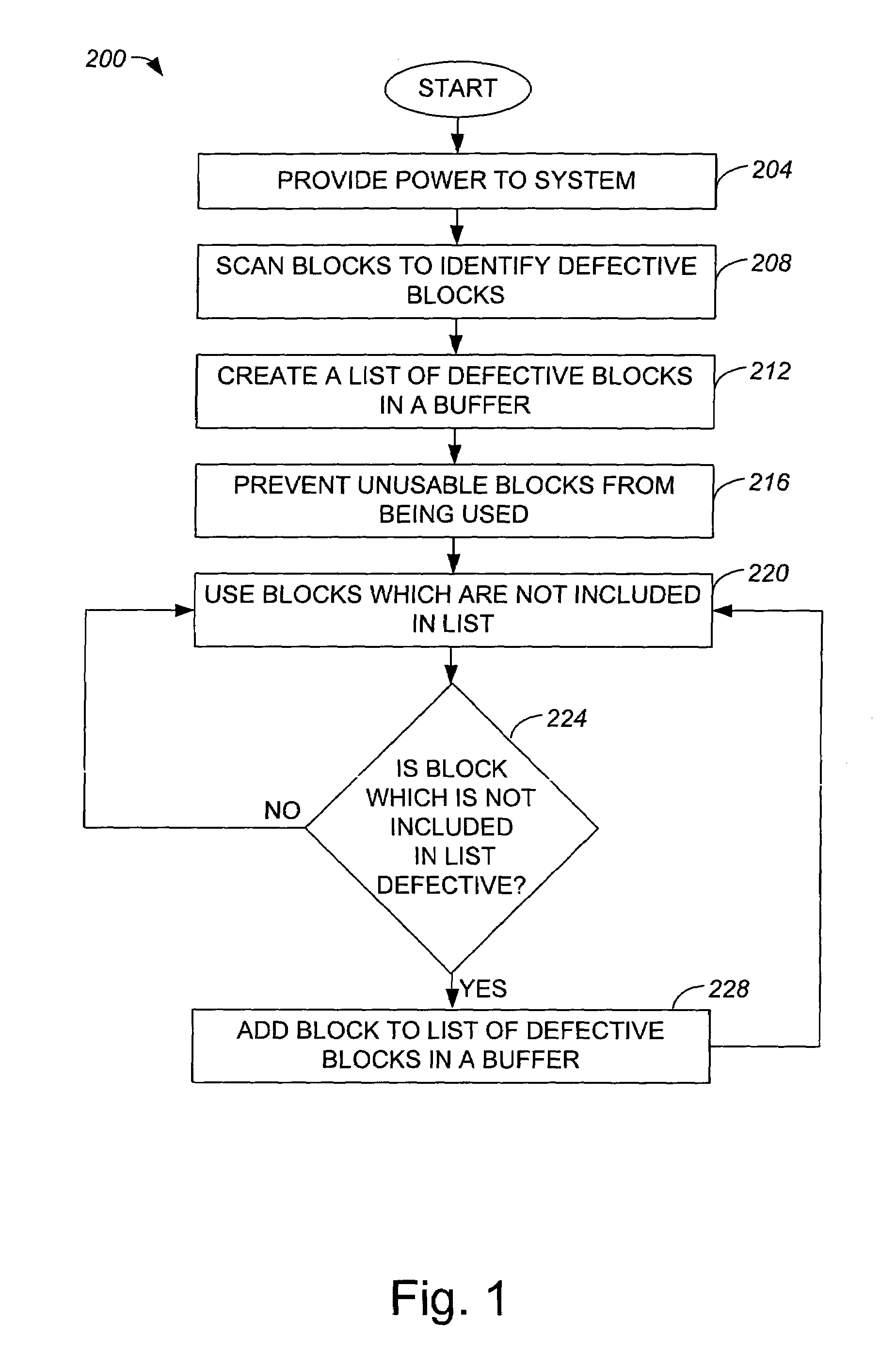
Defective blocks in a flash memory which include factory defects may be identified using a scanning process when power is applied to the flash memory.
While a scanning process identifies defective blocks, a scanning process generally does not differentiate between defective blocks with factory defects and defective blocks with growing defects.
By way of example, when a defective block which is not capable of holding data is used to store data, the data may be lost.
Typically, when a system is first powered up to be formatted, defective blocks include only blocks with factory defects, or defects which were first identified during a manufacturing process associated with the non-volatile memory.
Upon subsequent power up processes, defective blocks may include both blocks with factory defects and blocks with growing defects, or defects which arise during the course of the memory system being used.
Often, the list is created in a volatile buffer associated with the memory system such that when power is removed from the memory system, the list is lost.
Also, the list of defective blocks generally does not differentiate between blocks which are defective due to factory defects and blocks which are defective due to growing defects.
Occasionally, a block which is not included in the list of defective blocks may not be successfully read from, successfully written to, or successfully erased.
In other words, a block which is not included in the list of defective blocks may be defective, as for example due to a growing defect which has arisen.
As a result, blocks which are actually usable may not be used, and the memory system may operate less efficiently as a result of an inability to use substantially all blocks which are usable.
For example, if a NAND flash memory is subjected to an environment of approximately 90 degrees Celsius, which is generally out of the specification range of most flash memories, many growing defects are typically detected.
At times, during the course of using a memory system which includes a flash memory component, it may be determined that the memory system does not have enough spare blocks available for use in storing data.
Obtaining additional flash memory components for use with the memory system may be time-consuming, as well as relatively expensive.
When there may be usable blocks which have been characterized as being unusable, it may be particularly inefficient to compensate for a lack of available spare blocks within the memory system, as some potentially usable blocks are effectively being wasted.

Method used


Image

  • Unusable block management within a non-volatile memory system
  • Unusable block management within a non-volatile memory system
  • Unusable block management within a non-volatile memory system

Examples


Embodiment Construction

[0036]When a memory system which includes a non-volatile memory has a pool of spare physical blocks which is being depleted, i.e., is running low, a user of the memory system may effectively be forced to compensate by the lack of available memory. For instance, a user may obtain additional non-volatile memory, which may be expensive. At times, physical blocks of a non-volatile memory which are identified as being unusable or defective in some environments may actually be suitable for use at a later time in a different environment. For example, physical blocks which have been identified as being unusable due to growing defects may, upon the implementation of a thorough testing process with a rigorous pattern, be reclaimable. When there may be usable blocks which have been characterized as being unusable, some potentially usable blocks are effectively being wasted.

[0037]By reclaiming potentially usable blocks which have previously been identified as being unusable for use, substantial...


PUM


Abstract

Methods and apparatus for tracking defective blocks such that at least some of the defective blocks may be readily identified and tested for usability when desirable are disclosed. According to one aspect of the present invention, a method for identifying spare blocks within a non-volatile memory includes subjecting at least one defective physical block associated with the non-volatile memory to a test that is arranged to determine if the defective physical block is usable. The method also includes determining when the defective physical block passes the test, and identifying the defective physical block as a usable physical block when it is determined that the defective physical block passes the test.

Description

[0001]This patent application claims priority to U.S. Provisional Patent Application No. 60 / 421,965, filed Oct. 28, 2002, which is hereby incorporated by reference in its entirety.CROSS REFERENCE TO RELATED APPLICATIONS[0002]The present invention is related to co-pending U.S. patent application Ser. Nos. 10 / 281,739, 10 / 281,823, 10 / 281,670, 10 / 281,824, 10 / 281,631, 10 / 281,855, 10 / 281,762, 10 / 281,696, 10 / 281,626, and 10 / 281,804, as well as co-pending U.S. Provisional Patent Application Nos. 60 / 421,910, 60 / 421,725, 60 / 422,166, 60 / 421,746, and 60 / 421,911, each filed on Oct. 28, 2002, which are each incorporated herein by reference in their entireties.BACKGROUND OF THE INVENTION[0003]1. Field of Invention[0004]The present invention relates generally to mass digital data storage systems. More particularly, the present invention relates to systems and methods for enabling defective or unusable physical blocks to be managed such that defective blocks with growing defects may possibly be recl...

Claims


Application Information

Patent Timeline
Patent Type & Authority Patents(United States)
IPC IPC(8): G06F12/00G06F11/00G01R31/28G06F11/20G06F12/16G11C7/00G11C16/00G11C16/02G11C16/34G11C29/00G11C29/04G11C29/26G11C29/44G11C29/56
CPCG11C29/44G11C29/26G11C16/04G11C16/34
Inventor CHANG, ROBERT C.QAWAMI, BAHMANSABET-SHARGHI, FARSHID
Owner SANDISK TECH LLC
Why Eureka
Eureka Blog
Learn More