
Adjustable heavy bag/speed bag frame with piston assist

a technology of piston assist and heavy bag, which is applied in the field of easy and efficient adjustment of frame with platform and structural members, can solve the problems of heavy and awkward control, and achieve the effect of easy control of the descent, heavy and awkward control

Inactive Publication Date: 2008-09-11
TECHN KNOCKOUT
View PDF10 Cites 16 Cited by
  • Summary
  • Abstract
  • Description
  • Claims
  • Application Information

AI Technical Summary

Benefits of technology

[0010]While, exercise equipment utilizing adjustable frames is used extensively in basketball goal systems, it also extends for use in boxing exercising apparatuses, and particularly the structures used to support the boxing bags. U.S. Pat. No. 6,220,992 B1 issued to Shafik discloses a boxing frame for both speed bags and heavy bags, which utilizes a multi-purpose bracket and pin assembly to position the height of the speed bag platform. This device is also for attachment to a tread mill. The disadvantage of the invention disclosed in the '922 patent is that the system uses a simple bracket and pin for adjusting the height of the speed bag. The bracket and pin adjustable members have a number of disadvantages including difficulty in removing the pin, and inconvenience in actually displacing the adjustable member within the bracket, particularly as the bracket becomes worn with continued use.
[0011]U.S. Patent Publication No. US2006 / 0025286 A1 issued to Shipes, discloses a rotatable frame assembly for a boxing heavy bag. The frame assembly consists of a rotatable shaft and a transverse member. The rotatable shaft is driven by a motor which can be remotely controlled. In rotating the shaft, the heavy bag is displaced, thereby mimicking the movements of an opponent. The main disadvantage of this invention is that the heavy bag height can not be adjusted based upon the preference of various users.
[0012]U.S. Pat. No. 5,050,866 issued to Fucci discloses a punching bag support frame with at least two (2) telescoping sections, one being a tooth / gear assembly and the second being an internal pressure safety cylinder within the main frame to assist with controllability of the unit. The pressure cylinder can be located, in an alternative embodiment, outside the main frame, and is designed to assist the rack and pinion gear assembly to ease movement of the upper assembly. The disadvantage of this invention is that the entire frame assembly is moved, so that if a heavy bag is also attached to the frame, the height of the heavy bag is adjusted with the height of the speed bag. Furthermore, in adjusting the main support frame, a powerful pressure cylinder must be used to drive the movement as the main support frame is rigid and extremely heavy.
[0013]However, none of the prior art references, either alone or in combination with one-another, teach or suggest the novel aspects of the instant invention, nor the mechanical designs relating to the secondary, independent and vertically adjustable speed bag frame that is attached to a main support frame. Consequently, there continues to exist a need for an efficient, simple, user friendly and structurally sound design for an adjustable frame for boxing speed bags or heavy bags. Furthermore, this design must allow for the independent adjustment of the height of various components that are attached to the main support frame.BRIEF SUMMARY OF THE INVENTION
[0014]The present invention relates to an improved design for manufacturing, assembling and using adjustable boxing frames for supporting speed bags or heavy bags. The adjustable support frame is conventional in that it includes a main support piece and two extension support assemblies that are used to attach a heavy bag and a smaller, generally circular speed bag to the main support piece. The entire assembly frame is supported by base members that sit on the floor and extend outwards from the bottom end of the main support piece. The pieces that are used to support both the speed bag and heavy bag are rigidly secured to the main support piece, so that in operation of the bags displacement of the entire frame is assembly is neutralized by the base members.
[0015]The speed bag support assembly includes a sliding bracket that encloses a vertical strut that is attached to an extension piece. The sliding bracket is attached to a platform support member that extends horizontally out of the sliding bracket. The platform, upon which the speedbag is attached to and operated on, extends from the bottom of the platform support member. The platform, platform support member and sliding bracket are all rigidly secured together, so that as the bracket is displaced vertically, the platform displaces with respect to the bracket. The displacement of the platform, in turn causes the adjustment of the height of the speed bag. The use of a displaceable bracket surrounding a strut piece that extends outward from the main support piece, allows the height of the speed bag to be adjusted independently from the rest of the entire support frame, thus fixing the height of the heavy bag.

Problems solved by technology

Furthermore, as the bracket is moved downward, the piston continues to apply an upward force, thus allowing the user to easily control the descent of the bracket and subsequent speed bag which can be heavy and awkward to control.

Method used


Image

  • Adjustable heavy bag/speed bag frame with piston assist
  • Adjustable heavy bag/speed bag frame with piston assist
  • Adjustable heavy bag/speed bag frame with piston assist

Examples


Embodiment Construction

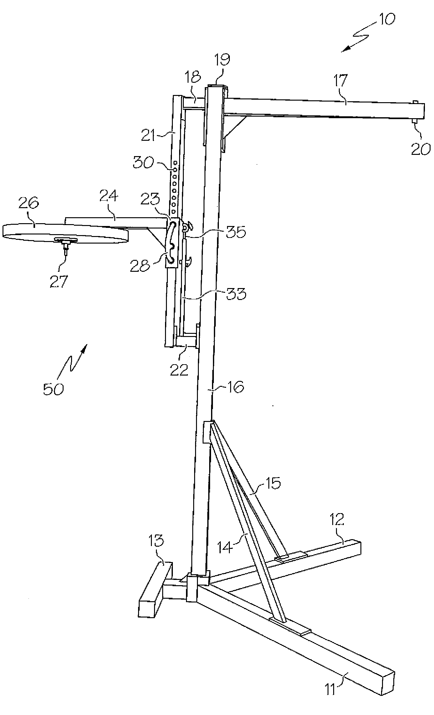
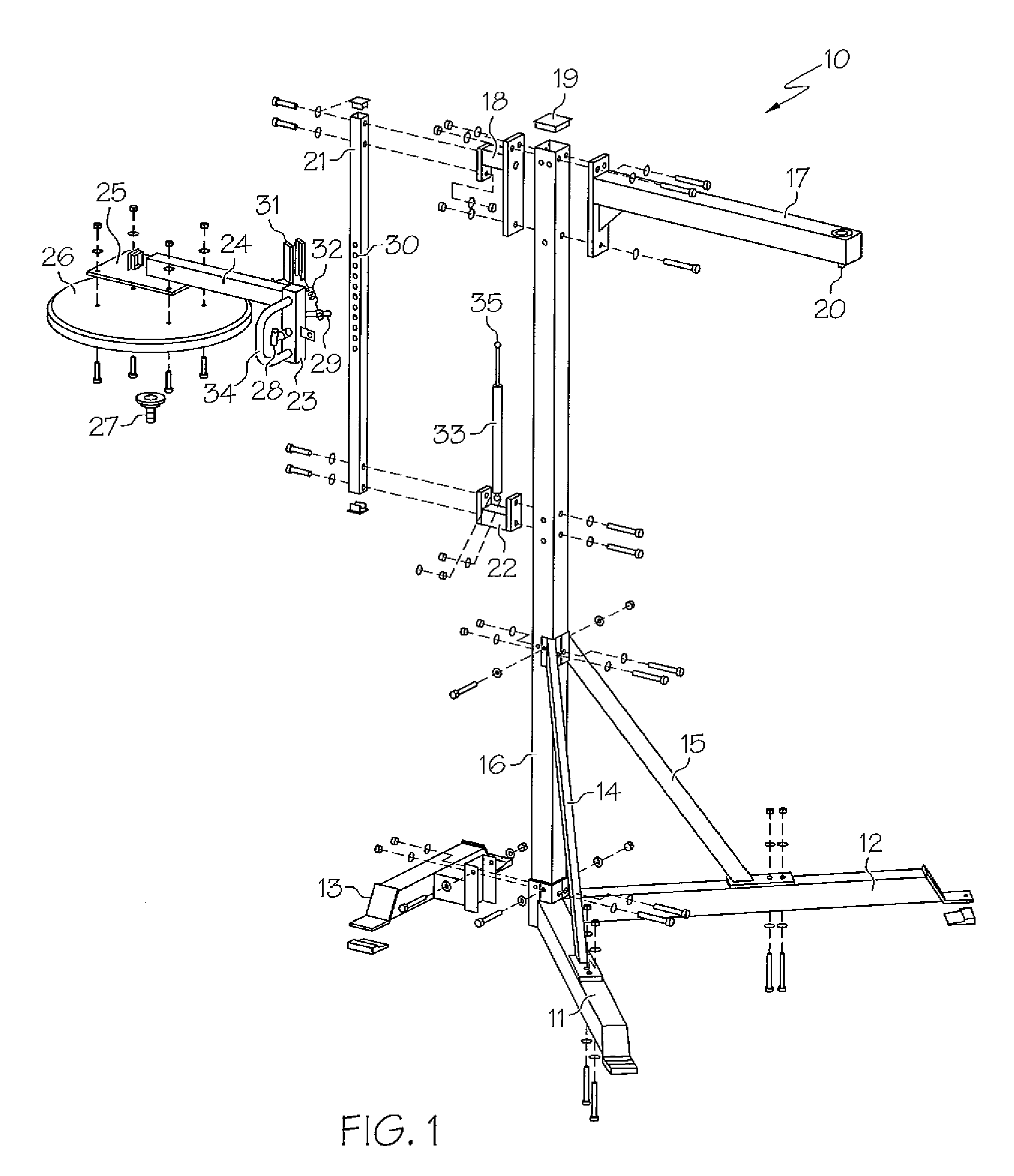
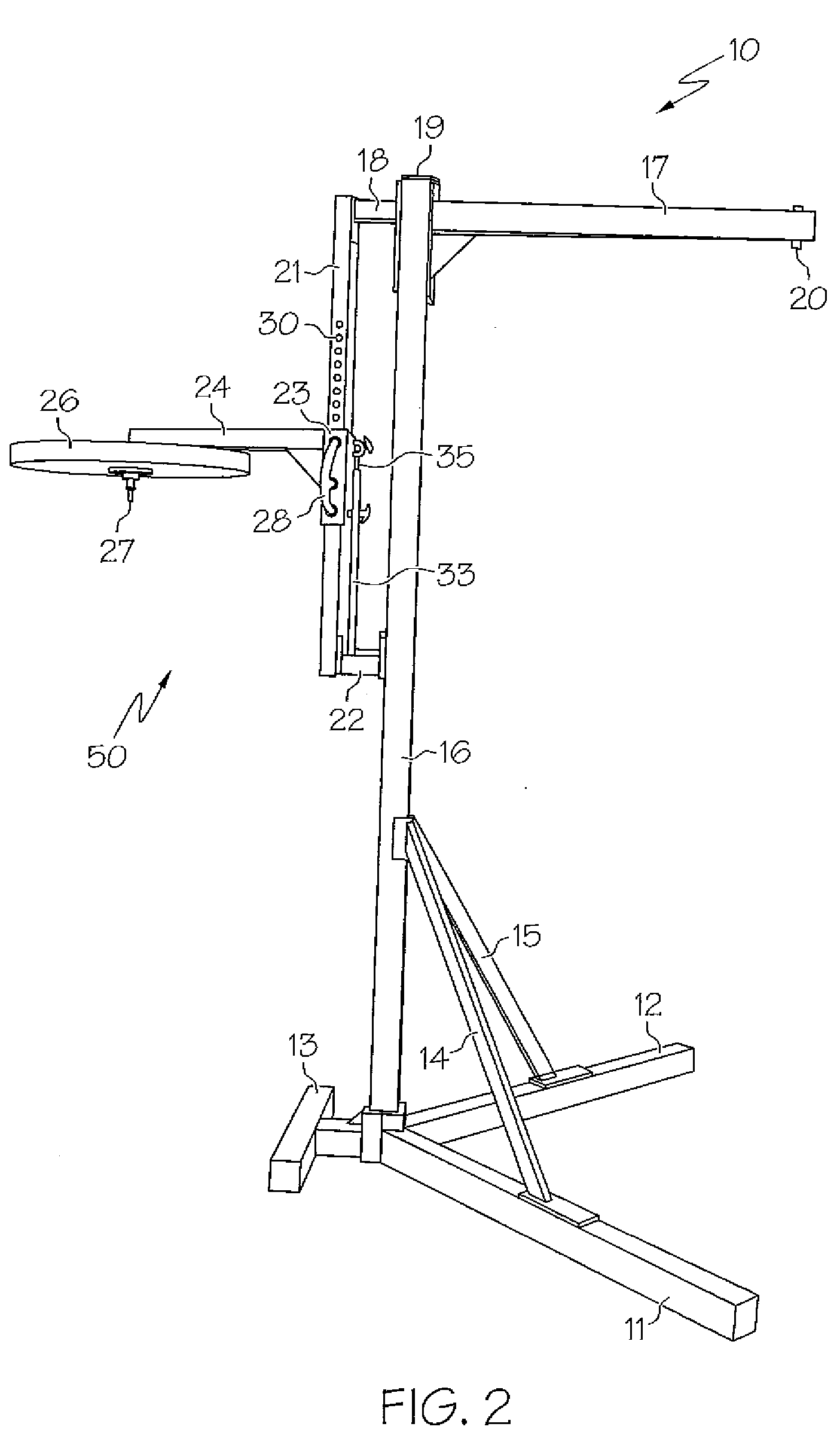
[0026]FIG. 1 illustrates an exploded view of the components of the preferred embodiment of the entire boxing frame 10, while FIG. 2 shows a side perspective view of the complete boxing frame 10. Referring to both FIGS. 1 and 2, the boxing frame consists of a main support piece 16 that extends vertically in a perpendicular direction to the surface upon which the boxing frame 10 rests upon. The main support piece 16 is constructed from any suitable high strength material that can be but is not limited to steel. The piece 16 is hollow to decrease the weight of the overall frame 10 and can be of any geometrical shape. In the preferred embodiment, the main support piece 16 is four sided to provide surfaces for the mounting of the additional components that make up the boxing frame 10.

[0027]A left and right base frame leg 12 and 11 and a base cross frame leg 13 are attached to the bottom of the main support member 16. The base legs 11, 12, and 13 limit the side to side displacement of the...


PUM


Abstract

A boxing equipment frame assembly, wherein the frame assembly is capable of supporting a plurality of punching bags including a speed bag and a heavy bag. The frame assembly includes a speed bag support assembly that includes a sliding bracket. The bracket serves as the means of connecting the speed bag support assembly to the main equipment frame. By using a sliding bracket that moves independently of the main support frame, the height of the speed bag can be adjusted without displacing any of the additional components attached to the frame. A piston is provided to apply a continuous upward force to the sliding bracket. In applying a continuous upward force the user has to put in less effort and a greater degree of control is achieved in adjusting the height of the speed bag.

Description

CROSS REFERENCE TO RELATED APPLICATIONS[0001]This utility application claims priority on and from U.S. Provisional Patent Application Ser. No. 60 / 893,708 filed on Mar. 8, 2007.STATEMENT REGARDING FEDERALLY SPONSORED RESEARCH OR DEVELOPMENTN / ABACKGROUND OF THE INVENTION[0002]1. Field of the Invention[0003]The present invention relates to boxing equipment and more particularly pertains to an easily and efficiently adjustable frame with platforms and structural members which can support a heavy bag and a speed bag. The present invention is user friendly in that it allows for relatively quick and simple adjustments in the height of the platform which supports a boxing bag.[0004]2. Description of Related Art[0005]Punching bags were originally used by boxers to improve overall punching techniques. Recently, punching bags are being used by people who are not boxers, but want to receive the strength and aerobic benefits achieved through performing the motion of punching. Furthermore, punchi...

Claims


Application Information

Patent Timeline
Patent Type & Authority Applications(United States)
IPC IPC(8): A63B69/22
CPCA63B69/201A63B69/205A63B2225/093A63B2071/0063A63B71/023A63B69/305A63B69/222
Inventor YANG, STEVE
Owner TECHN KNOCKOUT
Learn More