
Process for Urea Production and Related Plant

a technology of urea and production process, which is applied in the direction of liquid-gas reaction process, inorganic chemistry, cyanic/isocyanic acid, etc., can solve the problems of deleterious modification of the natural circulation provided in the entire, serious lack of balance, and inability to increase the production capacity of the synthesis reactor, etc., to achieve simple and cost-effective effect, high pressur

Active Publication Date: 2008-09-11
CASALE SA
View PDF7 Cites 4 Cited by
  • Summary
  • Abstract
  • Description
  • Claims
  • Application Information

AI Technical Summary

Benefits of technology

[0017]The technical problem forming the basis of the present invention is that of devising and providing a process for urea production of the so-called stripping process type considered above, and more specifically of providing the high pressure loop thereof, capable of overcoming the limitations and / or drawbacks quoted with reference to the prior art, in a simple and cost-effective manner.
[0019]In this way it is possible, with great advantage, to rapidly vary the production capacity of a plant for the urea production by simply varying the parameters (pressure and / or flow rate) of a pump used for the aforementioned pumping to the operative steps of decomposition and stripping.

Problems solved by technology

Indeed, it is practically impossible to increase the production capacity of the synthesis reactor without causing serious lacks of balance in the circulation of the flows between synthesis reactor, stripper and condenser, i.e., basically, any variation of the designed pressure drops deleteriously modifies the natural circulation provided in the entire substantially isobar loop.
In other words, the aforementioned pressure difference of 1 bar is no longer sufficient to counteract the pressure drops due to the increase in capacity and therefore it is no longer possible to make the flow circulate again through the apparatuses of the high pressure loop.
Other drawbacks of the vertical layout of the aforementioned apparatuses are those linked to the construction costs of the raising that is necessary to the synthesis reactor and to the difficulties in maintaining the reactor itself raised with respect to the ground level.

Method used


Image

  • Process for Urea Production and Related Plant
  • Process for Urea Production and Related Plant
  • Process for Urea Production and Related Plant

Examples


Embodiment Construction

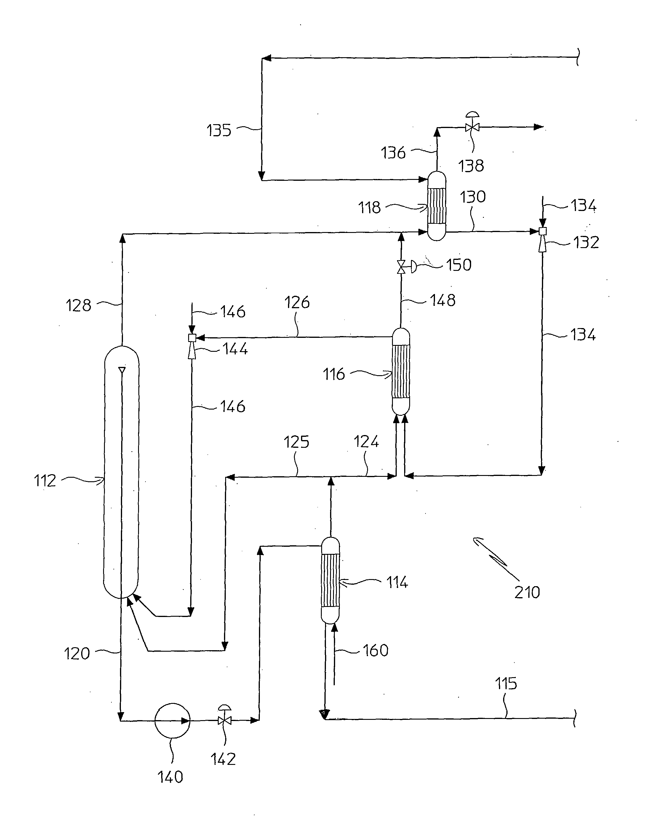
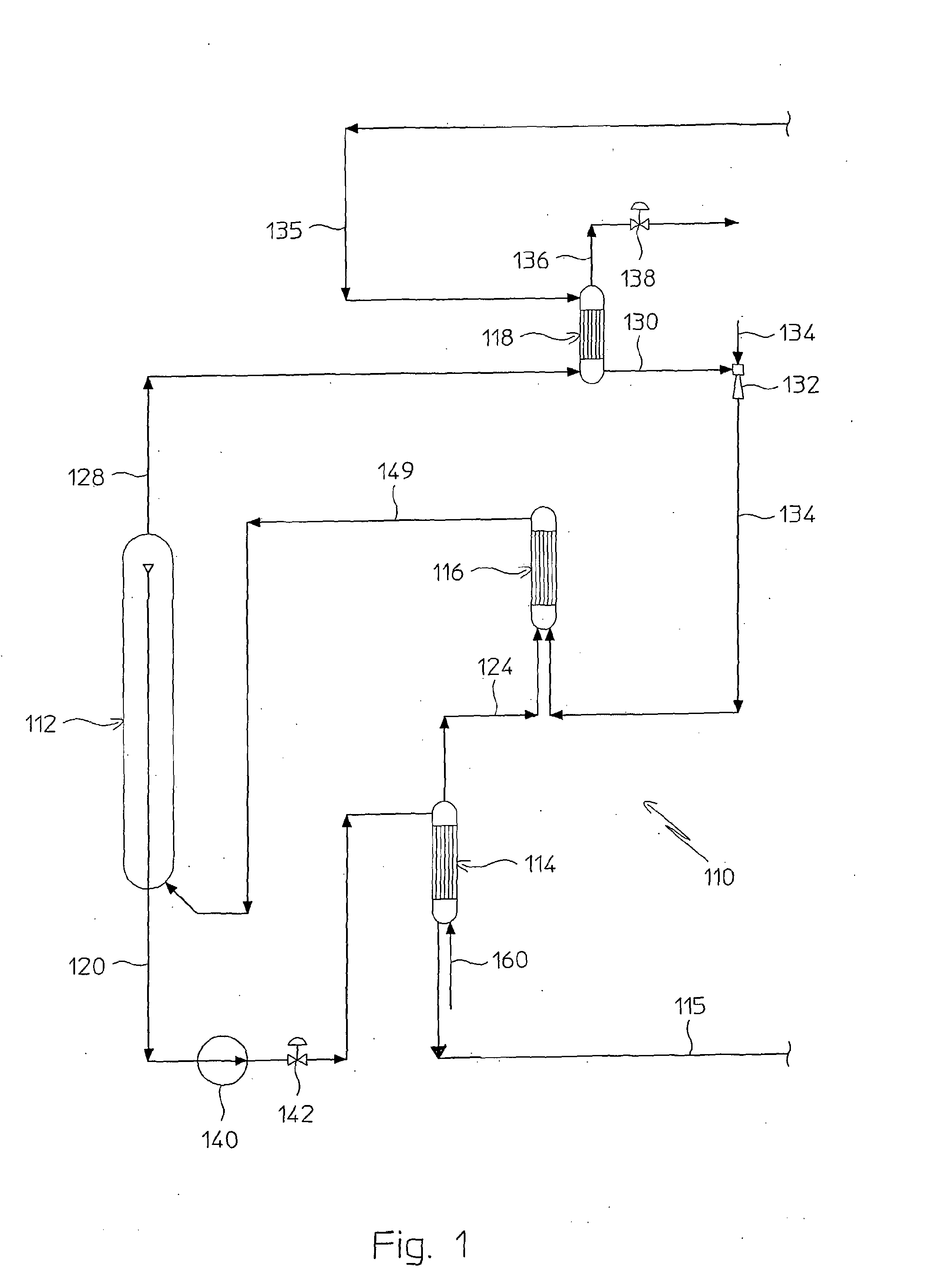
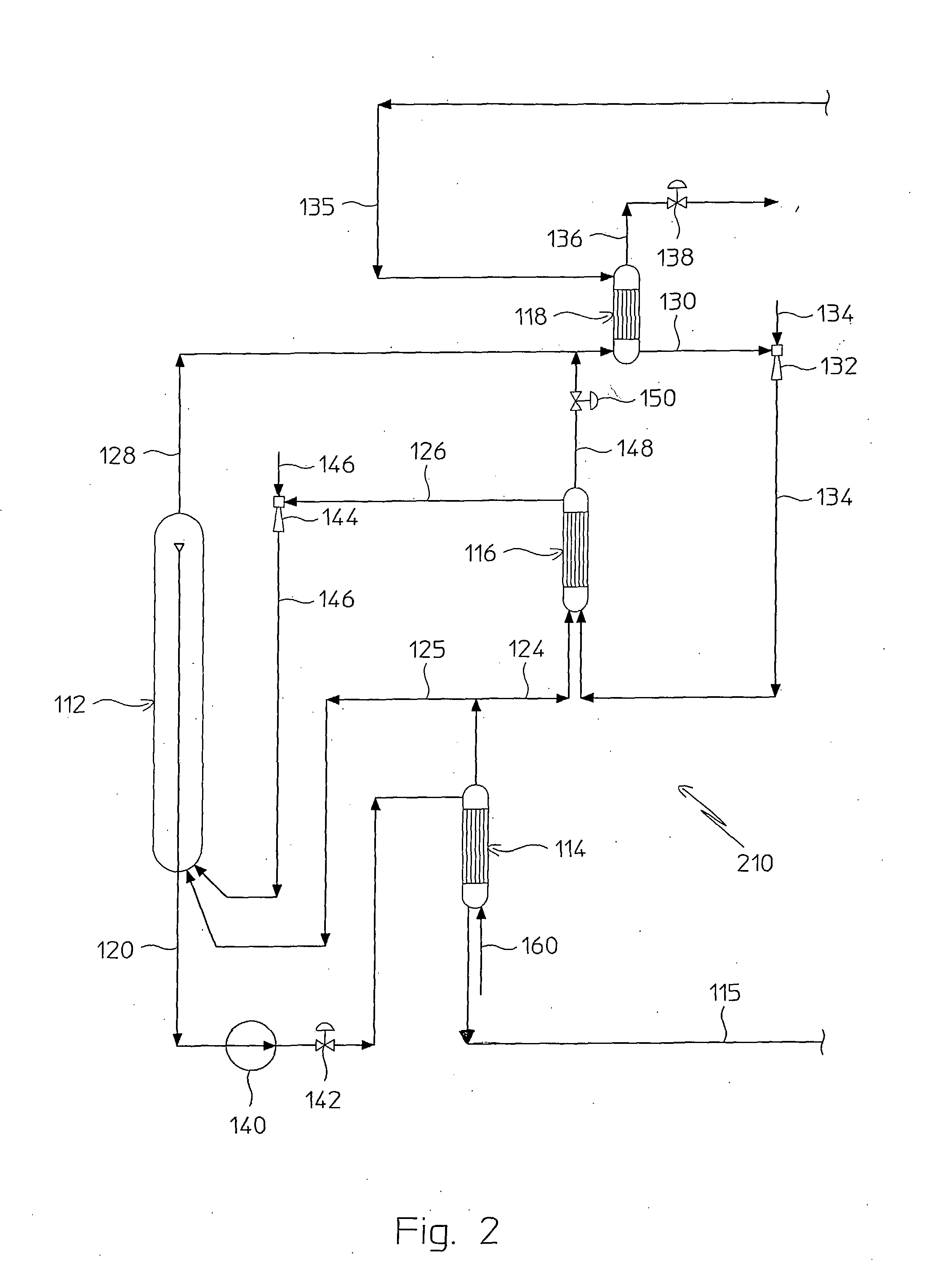
[0025]In order to simplify the description, only a portion of a plant for urea production that carries out the process of the present invention is shown schematically in the figures; more specifically, the high pressure urea synthesis section is shown, globally indicated with 110 (FIG. 1) and with 210 (FIG. 2), the remaining sections of the plant not being significant for the purposes of understanding the invention itself.

[0026]With reference to the aforementioned figures, the process for urea production according to the present invention comprises a first operative step in which ammonia and carbon dioxide are made to react at a predetermined high pressure in an appropriate synthesis reactor 112, obtaining a reaction mixture comprising urea, ammonium carbamate and free ammonia in aqueous solution.

[0027]From this aqueous solution, produced by the synthesis reaction and discharged by the synthesis reactor 112 substantially at the same high pressure at which said reaction is carried ou...


PUM

PropertyMeasurementUnit
Pressureaaaaaaaaaa
Heightaaaaaaaaaa

Abstract

A process for urea production from ammonia and carbon dioxide, made to react at a predetermined high pressure in an appropriate synthesis reactor (112), from the reaction between NH3 and CO2 being obtained a reaction mixture comprising urea, ammonium carbamate and free ammonia in aqueous solution, from which a recovery of ammonium carbamate and ammonia is carried out with their subsequent recycle to the synthesis reactor (112), said recovery from the reaction mixture taking place through operative steps of decomposition of the ammonium carbamate into NH3 and CO2 and of their stripping and a subsequent operative step of their recondensation into ammonium carbamate that is recycled to the synthesis reactor, the said reaction mixture obtained from the reaction between ammonia and carbon dioxide being pumped to the operative steps of decomposition and stripping.

Description

FIELD OF APPLICATION[0001]The present invention refers, in its most general aspect, to a process for urea production from ammonia and carbon dioxide, made to react at a predetermined high pressure in an appropriate synthesis reactor.[0002]In particular, the invention refers to a process of the aforementioned type in which a reaction mixture comprising urea, ammonium carbamate and free ammonia in aqueous solution is obtained from the reaction between NH3 and CO2, from which a recovery of ammonium carbamate and ammonia is carried out with their subsequent recycle to the synthesis reactor.[0003]More specifically the present invention concerns a process of the type considered, in which the aforementioned recovery from the reaction mixture takes place through operative steps of decomposition of the ammonium carbamate into NH3 and CO2 and of their stripping and a subsequent operative step of their recondensation (partial or total) into ammonium carbamate that is recycled to the synthesis ...

Claims


Application Information

Patent Timeline
IPC IPC(8): B01J19/00C07C273/04
CPCB01J2219/00006B01J2219/00103C07C273/04B01J2219/182B01J2219/185B01J2219/00108Y02P20/141B01J19/24C07C273/02C07C273/14
Inventor ROMITI, DOMENICOSTICCHI, PAOLO
Owner CASALE SA
Learn More