
Inline terminal, hub and distribution system

a technology of inline terminals and distribution systems, applied in stacking articles, ways, instruments, etc., can solve the problems of introducing significant delays, affecting the efficiency of the system,

Active Publication Date: 2008-09-11
MI JACK PRODS
View PDF20 Cites 32 Cited by
  • Summary
  • Abstract
  • Description
  • Claims
  • Application Information

AI Technical Summary

Benefits of technology

[0236]Keycards and the self-service nature of the system improve driver and crane operator productivity, and truck, buffer and crane utilization and efficiency.
[0237]A truck line carrier can easily load or unload a container to or from the buffer, while sitting in his or her cab by pressing a control button to operate the buffer. As should be understood, other means of actuation are contemplated and within the scope of this invention.
[0240]The self service operation can improve load pick up dwell times and load drop off dwell times over conventional terminals, which often require waiting or dead time.
[0242]Since the overhead gantry crane does not have to await for chassis delivery trackside, truck and crane operators can work independently, thus substantially reducing gating issues or unnecessary delays.
[0244]Terminal and distribution centers can realize enormous driver and chassis productivity gains, and eliminate bobtails and empty trips.
[0245]Equipping containers and truck operators with GPS, can improve container utilization and driver efficiency.

Problems solved by technology

Severe bottlenecks are seen in existing rail transfer terminals, which result in freight delays.
Most such terminals have little or no right-of-way available for terminal expansion.
Inefficiencies associated with moving containers from terminal to terminal by truck, to transfer between long-distance rail carriers (corridors), introduce significant delays, costs and inefficiencies.
Further, truck activity on urban and suburban freeways cause increased fuel consumption and pollution emissions.

Method used


Image

  • Inline terminal, hub and distribution system
  • Inline terminal, hub and distribution system
  • Inline terminal, hub and distribution system

Examples


Embodiment Construction

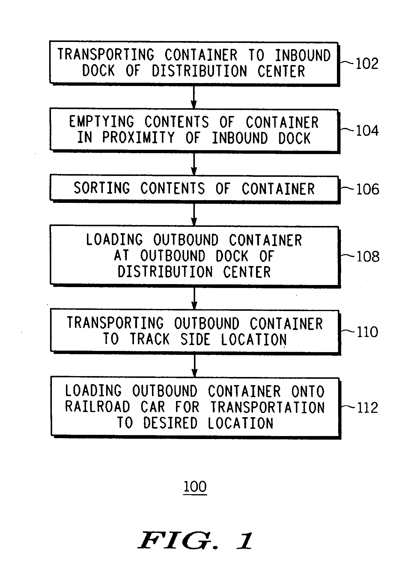
[0023]In its simplest form, an Inline Terminal, Hub and Distribution system and process flow diagram 100 is shown (hereafter referred to interchangeably as Inline Terminal, Inline System and / or Hub and Distribution System). Referring to FIG. 1, the system comprises the steps of: transporting 102 (hereafter the transporting or first transporting step 102) a container to an inbound dock of a distribution center; emptying 104 (emptying step 104) the contents of the container in proximity to the inbound dock; sorting 106 (sorting step 106) the contents of the container; loading 108 (loading step 108) an outbound container at an outbound dock of the distribution center; transporting 110 (transporting or second transporting step 110) the outbound container to a track side location; loading 112 (loading or second loading step 112) the outbound container onto a railroad car for transportation to a desired location. The system provides improved utilization of the available space and improved...


PUM


Abstract

An inline terminal system (300), which includes the steps of: (i) transporting (302) a first container with a cargo via an inbound railroad car to a terminal having a plurality of train rails; (ii) picking and placing (304) the first container from the railroad car to a track side location having at least one buffer in proximity to the plurality of train rails, including: (a) rotating the first container at an angle of at least ten or more degrees with respect to the train rails; and (b) positioning the at least one buffer substantially adjacent to the train rails, at the track side location, at an angle of at least ten or more degrees with respect to the train rails; and (iii) moving (306) the first container via a tractor truck to a desired location for unloading. This system provides a simple, robust and efficient method to load, and in the reverse unload, a container on a chassis or rail car, respectively.

Description

FIELD OF THE INVENTION [0001]This invention relates to transportation and logistics systems, and more particularly to an Inline Terminal, Hub and Distribution system.BACKGROUND OF THE INVENTION [0002]Freight transport continues to grow at a rapid pace, especially in the heavy-rail sector. Severe bottlenecks are seen in existing rail transfer terminals, which result in freight delays. Most such terminals have little or no right-of-way available for terminal expansion. Inefficiencies associated with moving containers from terminal to terminal by truck, to transfer between long-distance rail carriers (corridors), introduce significant delays, costs and inefficiencies. Further, truck activity on urban and suburban freeways cause increased fuel consumption and pollution emissions.[0003]In connection with transportation logistics, market forces are driving the development of new technologies to improve the efficiency of freight transfer operations at rail terminals. A rail ThruPort, which...

Claims


Application Information

Patent Timeline
IPC IPC(8): B65G57/02
CPCB61B1/005B61D47/00G06Q10/0833B65G65/00B65G63/004
Inventor LANIGAN, JOHN J.MIRABELLA, PETER W.TIPPIT, RAYHANNINEN, JOHN
Owner MI JACK PRODS
Learn More