
Battery Apparatus, Battery Control Apparatus, and Motor Drive Unit

a battery control and motor technology, applied in secondary cell servicing/maintenance, transmission monitoring, instruments, etc., can solve problems such as error-prone bit read and reception error

Active Publication Date: 2008-09-11
HITACHI ASTEMO LTD
View PDF1 Cites 24 Cited by
  • Summary
  • Abstract
  • Description
  • Claims
  • Application Information

AI Technical Summary

Benefits of technology

[0009]It is an object of the present invention to provide a battery apparatus, battery control apparatus, and motor drive unit that are capable of properly establishing serial communication even when a plurality of cell controllers and a battery controller are daisy-chained to form a serial communication configuration.
[0011]As the present invention is configured as described above, it can establish proper serial communication even when a plurality of battery module control apparatuses and the battery control apparatus are daisy-chained to form a serial communication configuration.
[0015]As the present invention is configured as described above, it can establish proper serial communication even when a plurality of battery module control apparatuses and the battery control apparatus are daisy-chained to form a serial communication configuration.
[0017]As the present invention is configured as described above, it can establish proper serial communication even when a plurality of battery module control apparatuses and the battery control apparatus are daisy-chained to form a serial communication configuration.
[0019]As the present invention is configured as described above, it can establish proper serial communication even when a plurality of battery module control apparatuses and the battery control apparatus are daisy-chained to form a serial communication configuration.
[0020]The present invention can establish proper serial communication even when a plurality of cell controllers and a battery controller are daisy-chained to form a serial communication configuration.

Problems solved by technology

This may cause an erroneous bit read and reception error.

Method used


Image

  • Battery Apparatus, Battery Control Apparatus, and Motor Drive Unit
  • Battery Apparatus, Battery Control Apparatus, and Motor Drive Unit
  • Battery Apparatus, Battery Control Apparatus, and Motor Drive Unit

Examples

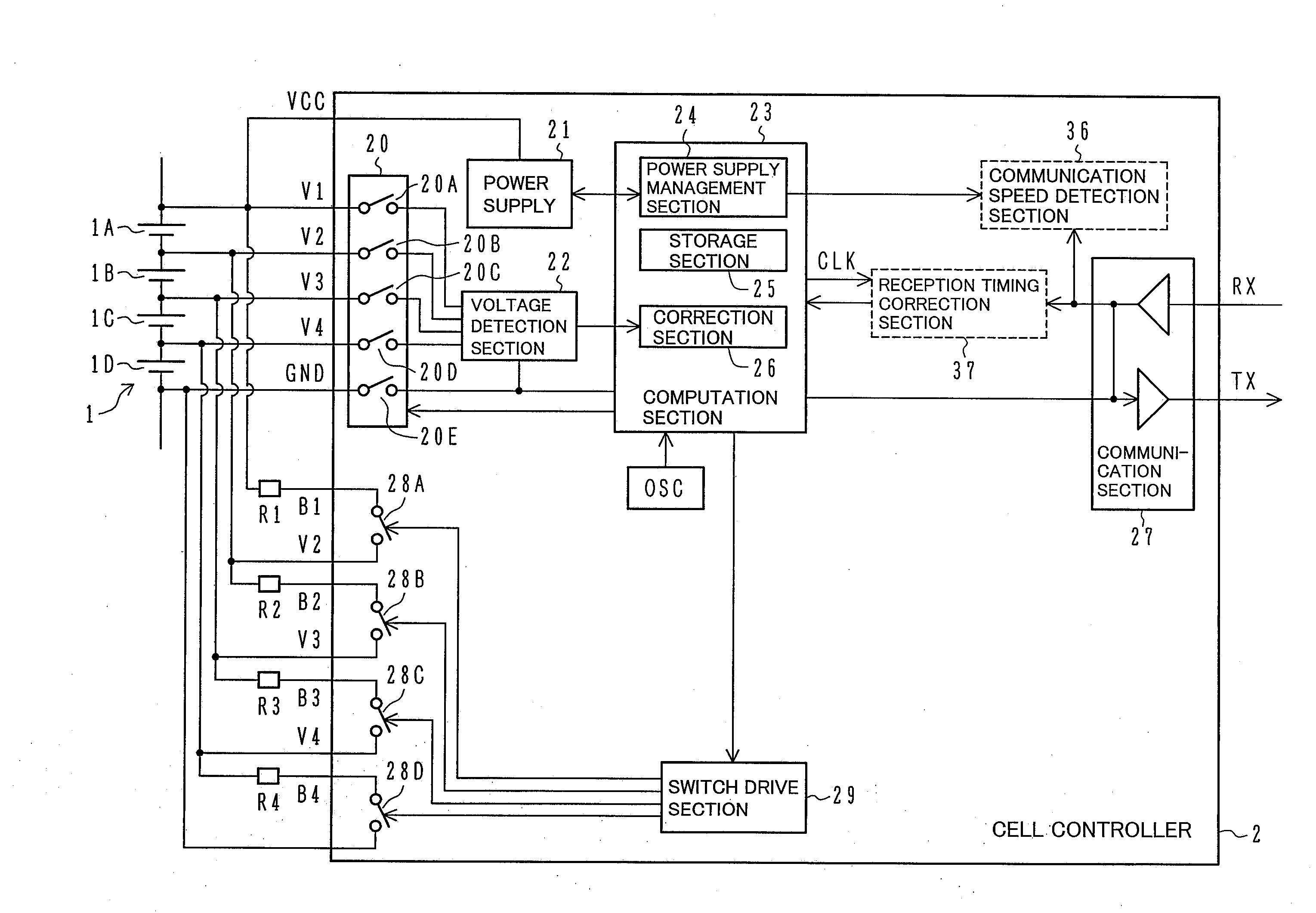
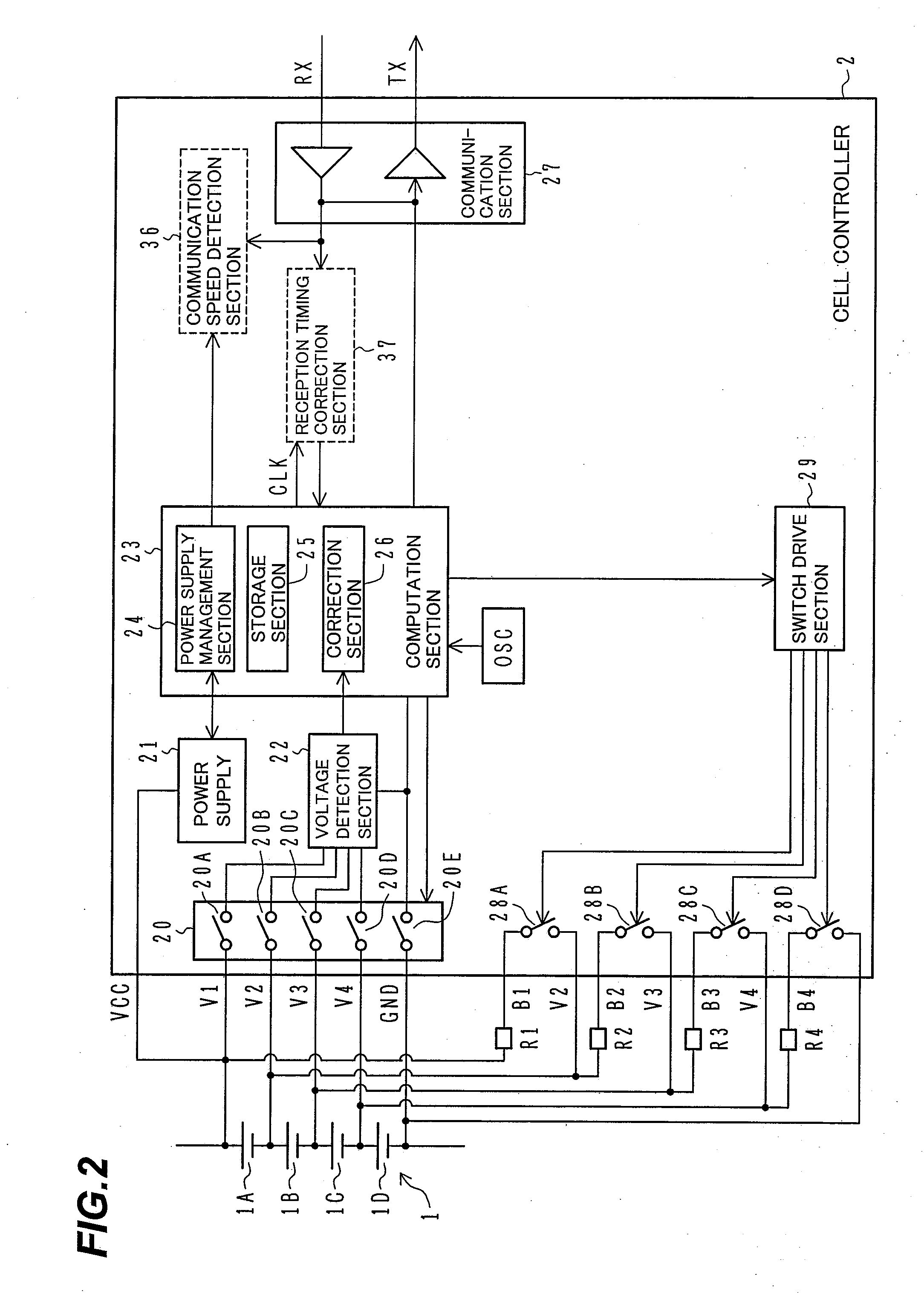

Embodiment Construction

[0029]The configuration and operation of a battery apparatus according to an embodiment of the present invention will now be described with reference to FIGS. 1 to 8.

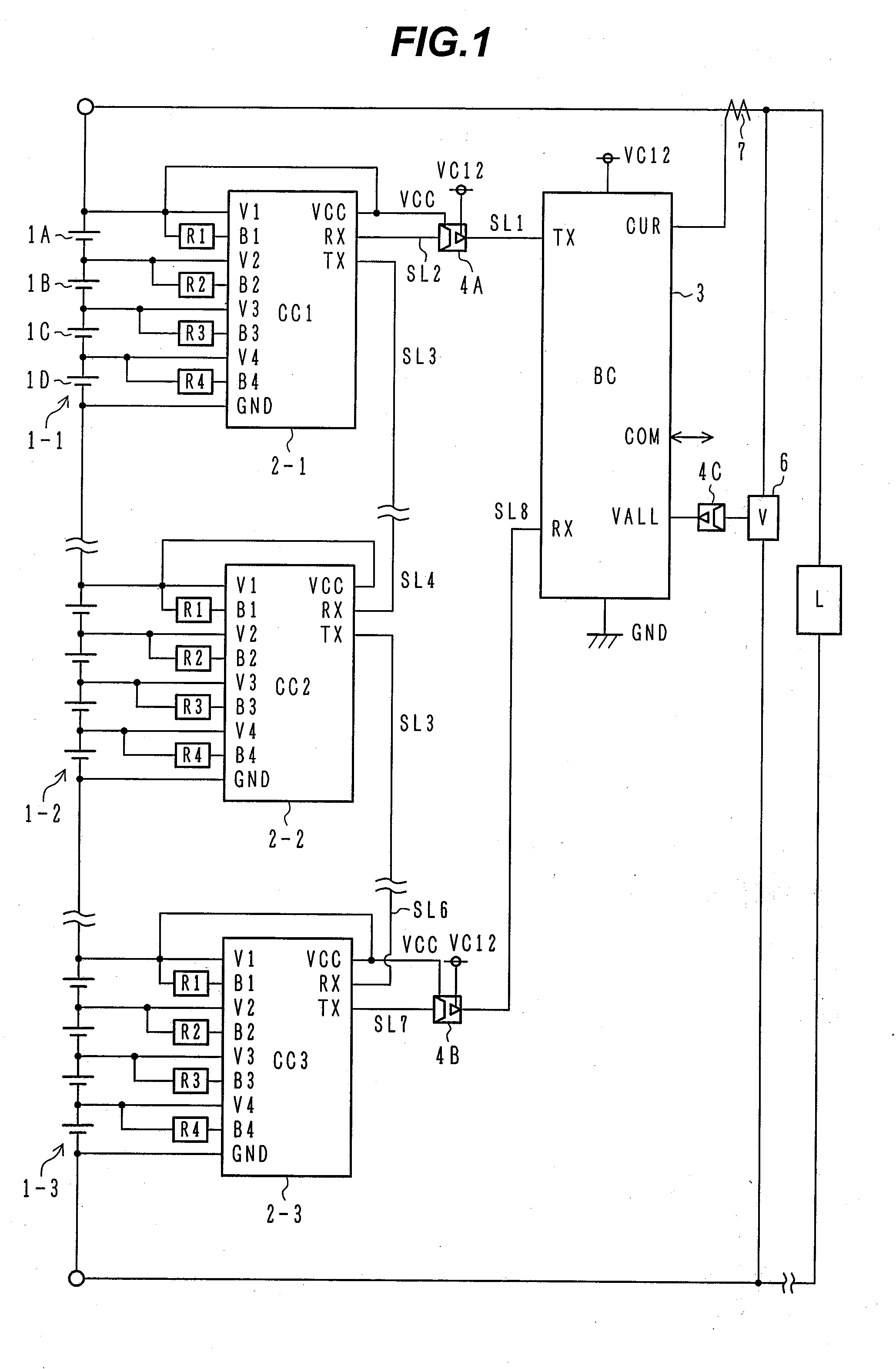
[0030]First of all, the overall configuration of the battery apparatus according to the present embodiment of the present invention will be described with reference to FIG. 1.

[0031]FIG. 1 is a block diagram illustrating the overall configuration of the battery apparatus according to an embodiment of the present invention.

[0032]Referring to FIG. 1, four battery cells 1A, 1B, 1C, 1D are series-connected to constitute one unit, which is called a unit battery cell (assembled battery) 1-1. For example, lithium batteries are used as the battery cells 1A, 1B, 1C, 1D. In such a case, the voltage of each battery cell 1A, 1B, 1C, 1D is 3.6 V. Therefore, the voltage of the unit battery cell 1-1 is 14.4 V.

[0033]Although FIG. 1 shows that three unit battery cells 1-1, 1-2, 1-3 are series-connected, the actual number of connected uni...


PUM


Abstract

The present invention provides enhanced serial communication reliability in a situation where a plurality of cell controllers and a battery controller are daisy-chained to form a serial communication configuration. While the plurality of cell controllers and the battery controller are daisy-chained to form a serial communication configuration, the battery controller or each cell controller includes a communication speed detection means, which detects the communication speed of data input from an additional controller, and a reception timing correction means, which corrects the reception timing for data input from the additional controller in accordance with the communication speed detected by the communication speed detection means.

Description

BACKGROUND OF THE INVENTION[0001]1. Field of the Invention[0002]The present invention relates to a battery apparatus, battery control apparatus, and battery module control apparatus that manage the status of an in-vehicle or power supply secondary battery (lithium storage battery), and a motor drive unit that uses the battery apparatus. More particularly, the present invention relates to a battery apparatus, battery control apparatus, and motor drive unit that are suitable for use with a daisy chain of a plurality of cell controllers for managing battery cells which constitute a storage battery, and a battery controller which manages the entire storage battery.[0003]2. Description of the Related Art[0004]In a hybrid vehicle or electric vehicle, an assembled battery composed of a plurality of battery cells is used for a battery apparatus. The cells of the assembled battery are divided into groups of predetermined number of cells, which are called battery modules.[0005]A conventional ...

Claims


Application Information

Patent Timeline
IPC IPC(8): H04B3/46
CPCB60L11/1868G01R31/3658Y02T90/16Y02T10/7066Y02T10/7005B60L58/20G01R31/396H01M10/425H01M2010/4271H01M2010/4278Y02E60/10Y02T10/70
Inventor KAWATA, TAKAHIROEMORI, AKIHIKOKAWAHARA, YOUHEIKUDO, AKIHIKO
Owner HITACHI ASTEMO LTD
Learn More