
Lens assembly and imaging device

Active Publication Date: 2008-09-11
NANCHANG O FILM OPTICAL ELECTRONICS TECH CO LTD
View PDF5 Cites 10 Cited by
  • Summary
  • Abstract
  • Description
  • Claims
  • Application Information

AI Technical Summary

Benefits of technology

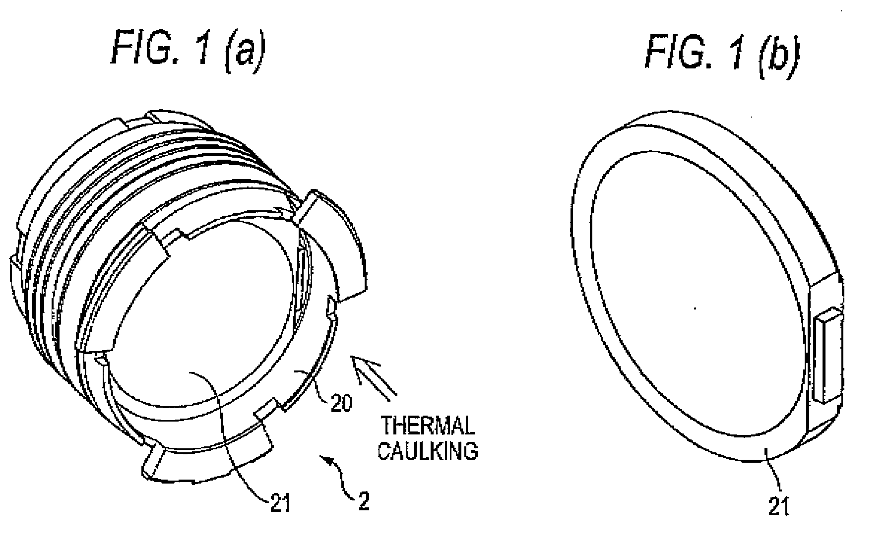
[0012]An object of an illustrative, non-limiting embodiment of the invention is to provide a lens assembly in which thermal caulking can be simply and surely performed even when a plastic lens is located inside a lens holder and to provide an imaging device having the lens assembly.
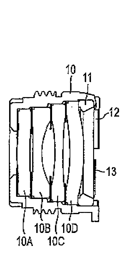
[0015]According to the above-described configuration, it is difficult for the heat to be transferred to a plastic lens even when thermal caulking is performed from the rear end face side since the spacer ring is inserted into the rearmost end face side and the spacer ring operates as a buffer member with the plastic lens, and the deformation of the plastic lens inside the lens holder is prevented. Moreover, the deformation of the lens holder itself is prevented since the flatness of a portion caught in a leading end of a thermal caulking tool is maintained by the spacer ring inserted into a more rear end face than a plastic lens of a D-cut shape even when the plastic lens of the D-cut shape is located in the rear end face side of the lens holder.
[0016]Since the plurality of lenses are accommodated within the lens holder by thermal caulking as described above, an unnecessary accommodating mechanism does not need to be provided in the lens holder, such that the miniaturization of the holder itself can be promoted.

Problems solved by technology

According to the above-described configuration, it is difficult for the heat to be transferred to a plastic lens even when thermal caulking is performed from the rear end face side since the spacer ring is inserted into the rearmost end face side and the spacer ring operates as a buffer member with the plastic lens, and the deformation of the plastic lens inside the lens holder is prevented.

Method used


Image

  • Lens assembly and imaging device
  • Lens assembly and imaging device
  • Lens assembly and imaging device

Examples


Embodiment Construction

[0030]Although the invention will be described below with reference to exemplary embodiments thereof, the following exemplary embodiments and modifications do not restrict the invention.

[0031]According to an exemplary embodiment of the invention, a lens assembly in which thermal caulking can be simply and surely performed even when a plastic lens is internally located and an imaging device having the lens assembly, can be realized.

[0032]Hereinafter, exemplary embodiments of the present invention will be described with reference to the accompanying drawings.

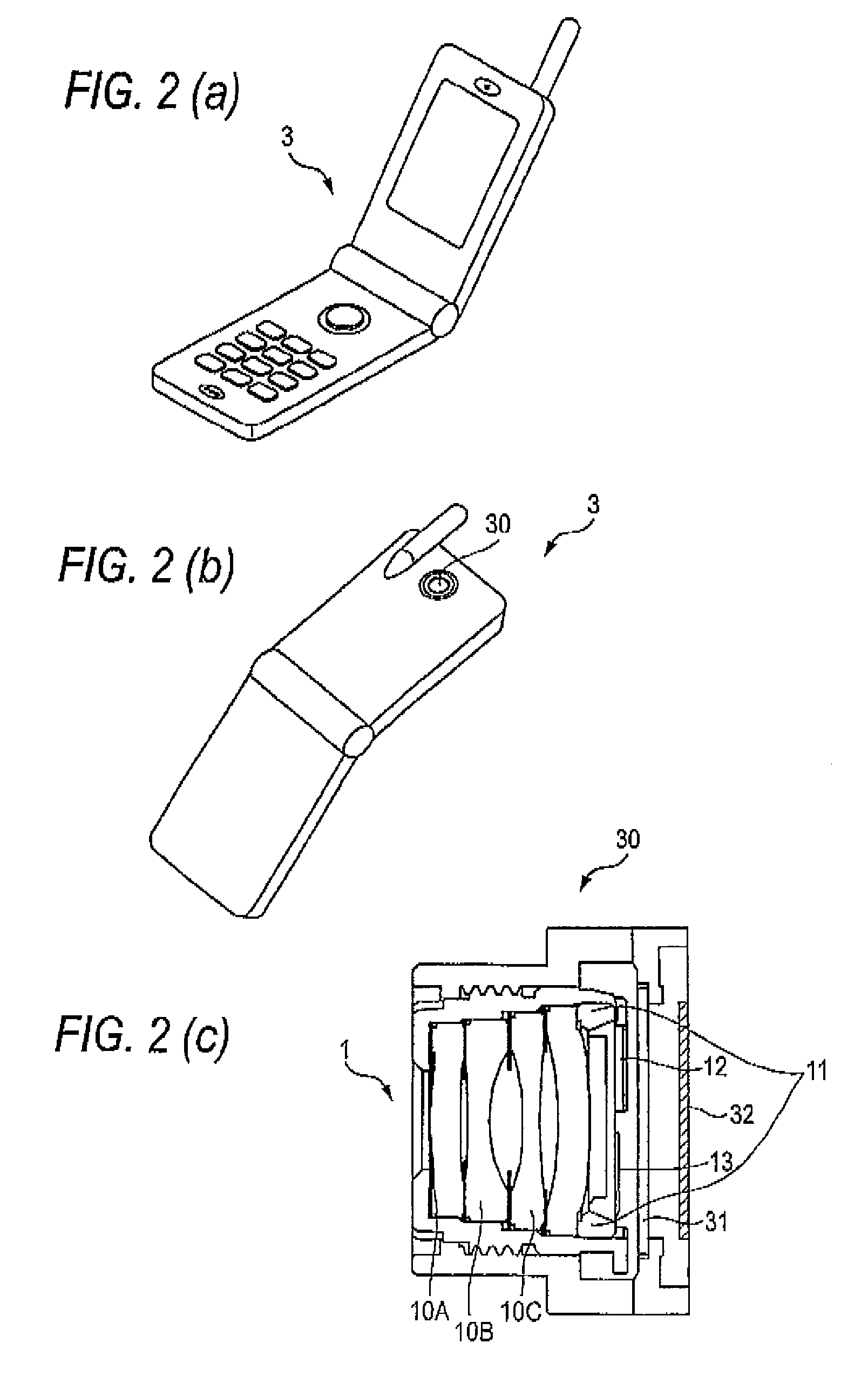
[0033]FIG. 2 is a view showing an outer appearance of a camera-equipped mobile phone 3 serving as an embodiment of an imaging device in which a lens assembly 1 of the present invention and an imaging element are incorporated. An imaging device 30 shown in FIG. 2C is incorporated in the camera-equipped mobile phone 3 shown in the FIGS. 2A and 2B. In the imaging device 30 shown in FIG. 2C, the lens assembly of the present invention,...


PUM


Abstract

A lens assembly includes: a lens group including a plurality of lenses; and a lens holder accommodating the lens group and having an opening in each of a front end face of the lens holder and a rear end face of the lens holder. The opening of the front end face has a smaller diameter than an outer diameter of a foremost lens accommodated in a foremost end face side of the lens holder, the lens holder includes a spacer ring disposed on a rear side of a rearmost lens accommodated in a rearmost end face side of the lens holder, the spacer ring abutting on a peripheral portion of the rearmost lens to keep a space between a rear face of the rearmost lens and the rear end face of the lens holder, and the lens holder holds a rear face of the spacer ring by thermal caulking.

Description

BACKGROUND OF THE INVENTION[0001]1. Field of the Invention[0002]The present invention relates to a lens assembly for accommodating a plurality of lenses and an imaging device having the lens assembly.[0003]2. Description of Related Art[0004]There is known a lens assembly in which an imaging lens for imaging subject light to a sensor of an imaging element or the like is internally incorporated. Among such a lens assembly, there is a lens assembly in which the miniaturization is promoted by simplifying a structure of an engaging portion of a lens holder and a lens frame by providing a male screw and a female screw to be precisely screwed together in the lens holder and the lens frame, and both optical axis alignment and focus adjustment is simply performed by threading the lens frame into the lens holder. Since this structure is highly miniaturized, the lens assembly is suitable to be mounted in a portable device, a vehicle, or the like.[0005]When a mechanism for fixing the lens frame...

Claims


Application Information

Patent Timeline
IPC IPC(8): G02B7/02
CPCG02B7/021H04N5/2254G02B7/026H04N23/55
Inventor TAKASE, YOSHIYUKI
Owner NANCHANG O FILM OPTICAL ELECTRONICS TECH CO LTD
Learn More