
Goggles for Improved Ocular Vision

a technology of ocular vision and goggles, which is applied in the direction of optics, instruments, lens assemblies, etc., can solve the problems of affecting the diagnostic and medical procedure of a person, affecting the diagnostic and medical procedure, and affecting the vision of a person

Inactive Publication Date: 2008-09-11
TECHNION RES & DEV FOUND LTD
View PDF18 Cites 52 Cited by
  • Summary
  • Abstract
  • Description
  • Claims
  • Application Information

AI Technical Summary

Benefits of technology

[0015]thereby allowing focusing into or out of said at least one eye or both.
[0032]sealing the vessel to the face around said at least one eye of the subject; thereby allowing focusing into or out of said at least one eye or both.

Problems solved by technology

Optical aberrations can impede a person's vision and interfere with diagnostic and medical procedures.
This blurs severely the details available to the eye.
In addition, the tear film and crystalline lens vary with time, further affecting the spot size.
In addition to affecting a person's eyesight, poor optical conditions can also reduce the effectiveness of eye examinations and treatment.
This significantly limits his or her ability to locate early warning signs of abnormalities, diagnose ocular diseases, or perform follow-ups on eye operations.
Corneal aberrations also interfere in the examination and treatment of other parts of the eye, such as the aqueous humour and the crystalline lens.
An eye surgeon applying a laser beam to the retina to treat the eye is limited by optical aberrations which result in a large beam spot, thereby causing neighboring areas of the retina to be heated and unnecessarily damaged.
And, because of limitations on his or her own view, the surgeon might not even be aware of these damages.
The device also keeps the lids open during the surgery, but it causes great inconvenience to the patient.
The optically measuring devices suffer less from the aberrations, but have a limited resolution nevertheless.
Unfortunately, all of these methods are rather complicated and the instrumentation takes up large volume.
The equipment used is cumbersome, expensive, and many parts of the technology are still immature.
But the price to be paid is a loss of magnification, and even demagnification of the observed—or laser treated—portions of the retina or the iris.
The largest disadvantage of this method is the need to add very strong positive lenses next to the flat goggles.
Without this external compensation, the magnifying power of the eye is lost, both for the person wearing the goggles and for the doctor looking into the eye, or operating on it.

Method used


Image

  • Goggles for Improved Ocular Vision
  • Goggles for Improved Ocular Vision
  • Goggles for Improved Ocular Vision

Examples


Embodiment Construction

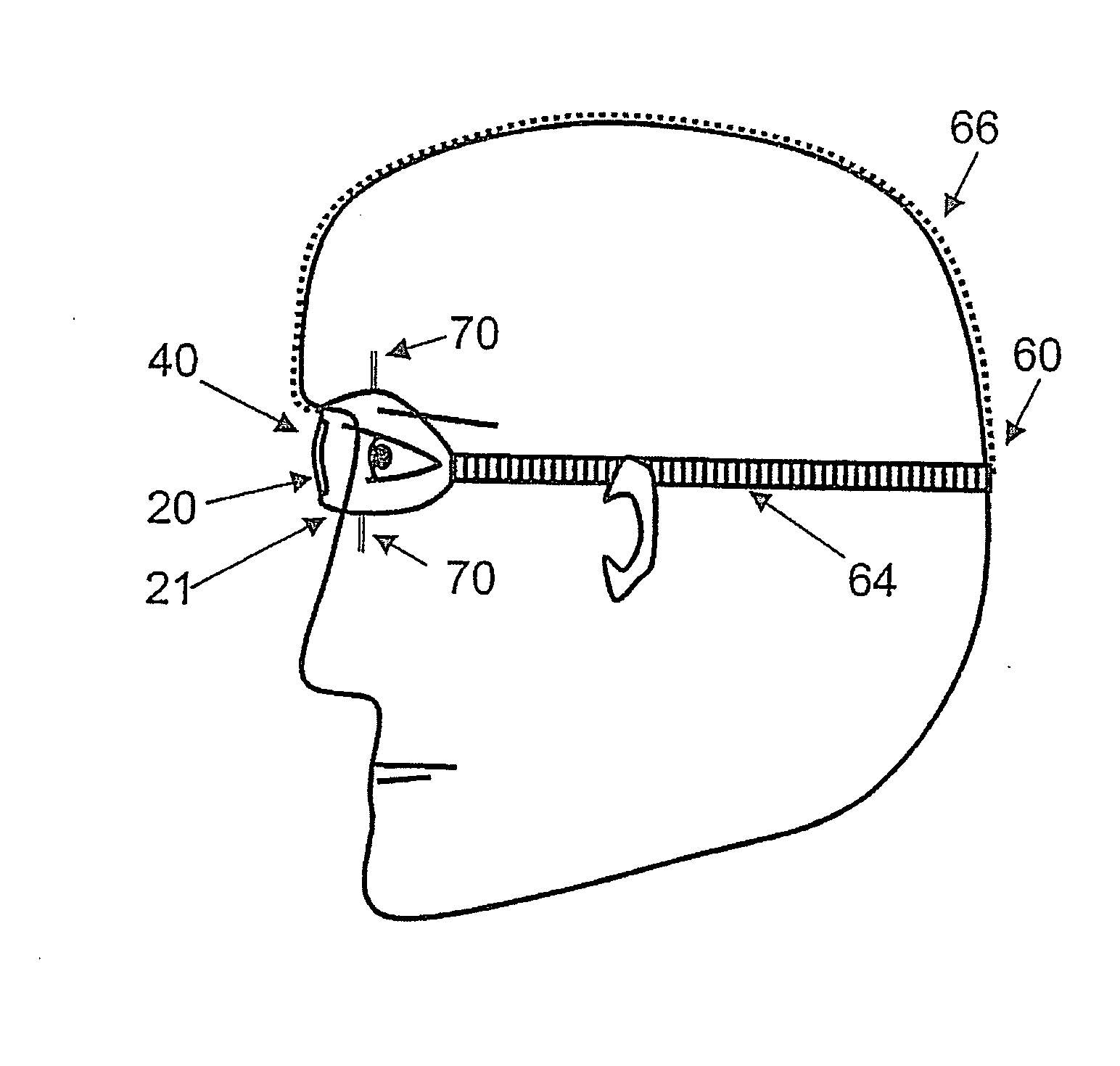
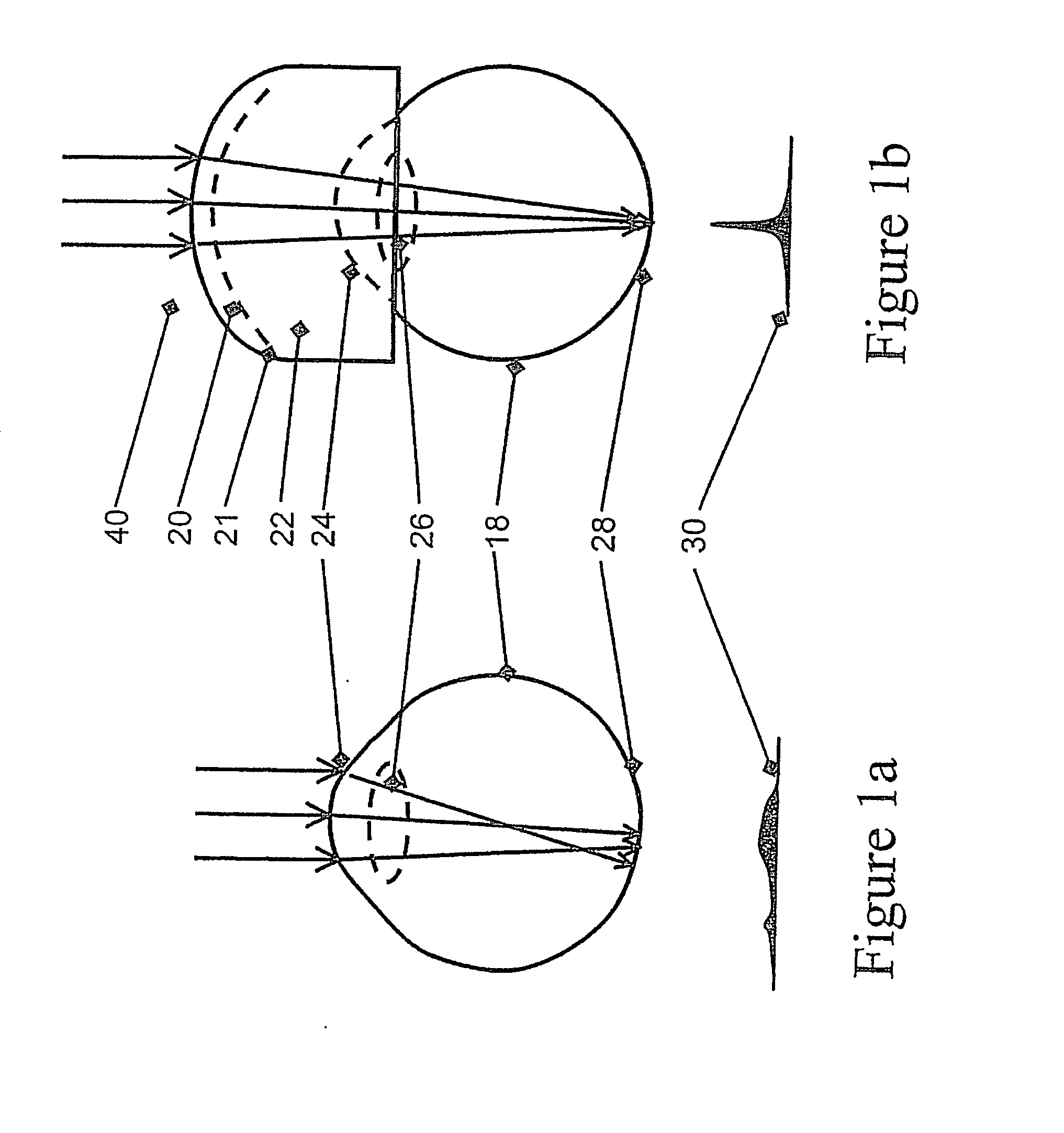
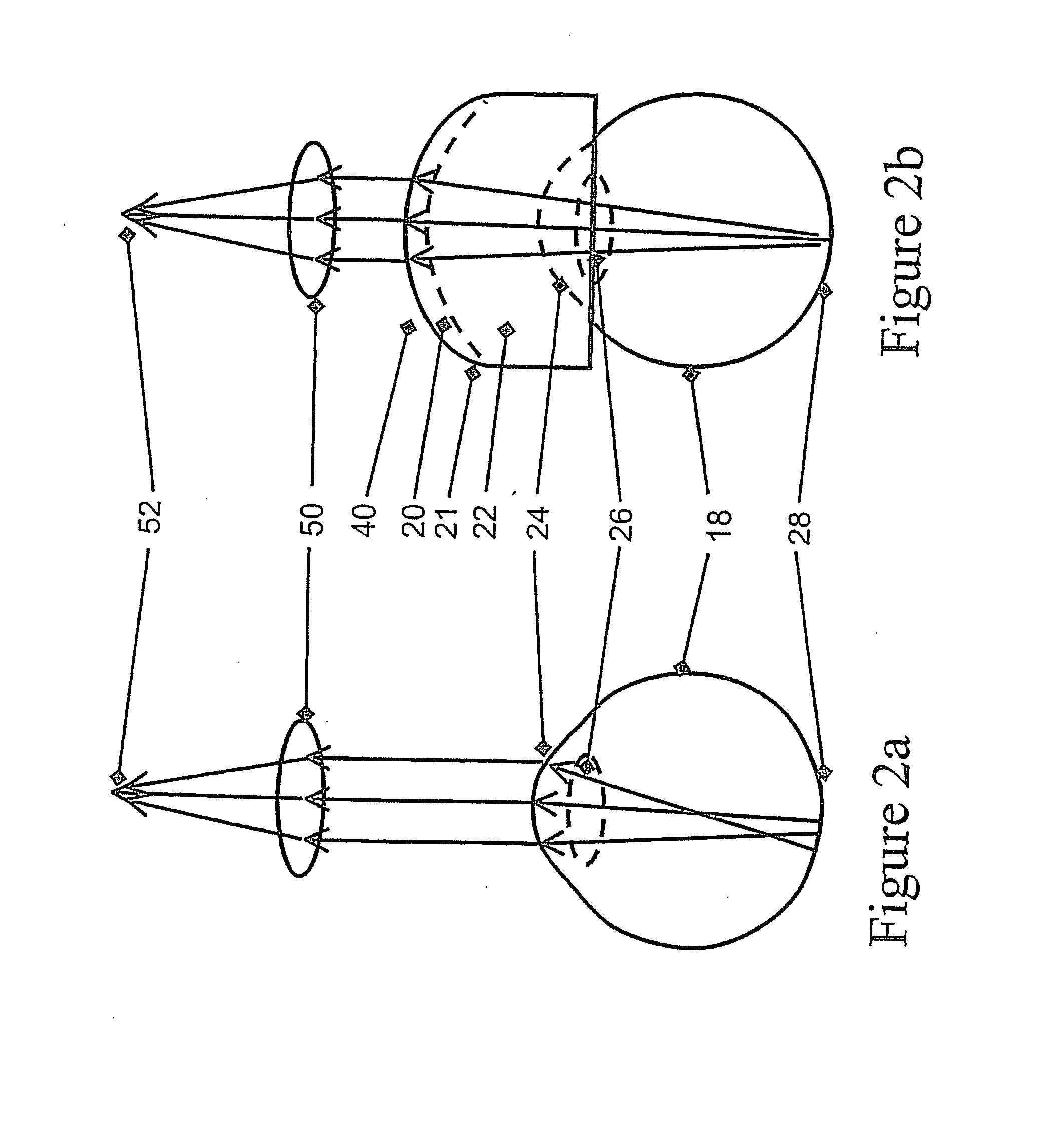
[0053]The present invention provides a solution to reduced vision acuity caused by aberrations in the cornea and the tear film. The invention comprises goggles filled with a substance having a refractive index matched to the refractive index of the cornea and worn over one or both eyes. The front window or lens of the goggles is perfected in order to allow high resolution vision both into the eye and out of it.

[0054]The goggles of the present invention have many uses in the field of ophthalmology. Principal uses include:[0055]Subjects with impaired vision can wear the goggles as eyeglasses, thereby improving their focus.[0056]Ophthalmologists and health care technicians can have their patients wear the goggles, thereby improving the focus spot size for examinations. The patient can wear the goggles alone or integrated into the examination apparatus, for example, as part of the head restraint or the front end of a fundus camera.[0057]Eye surgeons can have their patients wear the gogg...


PUM


Abstract

A device for improved vision into or out of at least one eye of a subject. The device comprises an enclosing vessel for holding one or more lenses in front one or two eyes of the subject and for holding a substance whose refractive index is matched to the refractive index of the cornea. The vessel is adapted to seal the substance to the face around the eye or eyes of the subject thereby allowing focusing into or out of the eye or eyes.

Description

FIELD OF THE INVENTION[0001]The present invention relates to improved ocular vision devices, methods of their fabrication, implementations and uses thereof. Specifically, the present invention relates to liquid filled goggles whose front lens (or window) is designed to focus into the eye and out of it, while the immersion substance nulls or reduces aberrations of the cornea.BACKGROUND OF THE INVENTION[0002]Optical aberrations can impede a person's vision and interfere with diagnostic and medical procedures. Most optical aberrations occur in the cornea and the tear film, with additional contribution from the crystalline lens and marginally from the ocular humours. In the case of dilated pupils, the actual focus spot size on the retina is in the range of 20-100 micrometers, instead of the theoretical range of 1-2 micrometers. This blurs severely the details available to the eye. In addition, the tear film and crystalline lens vary with time, further affecting the spot size.[0003]In ad...

Claims


Application Information

Patent Timeline
Patent Type & Authority Applications(United States)
IPC IPC(8): G02C7/04G02C11/04
CPCA61F9/022
Inventor RIBAK, EREZ
Owner TECHNION RES & DEV FOUND LTD
Learn More