
Volatile liquid droplet dispenser device

a dispenser device and liquid droplet technology, applied in the direction of positive displacement liquid engines, movable spraying apparatus, machines/engines, etc., can solve the problems of inability to take a total device approach to the industrial production and assembly of components and devices, inability high cost, etc., to achieve the lowest possible cost, easy to exchange the reservoir, and simple and inexpensive

Inactive Publication Date: 2008-09-11
APTAR FRANCE SAS
View PDF33 Cites 19 Cited by
  • Summary
  • Abstract
  • Description
  • Claims
  • Application Information

AI Technical Summary

Benefits of technology

[0035]Thus, the present invention concerns the construction of an innovative and inventive dispenser device fulfilling these objectives efficiently and in various embodiments which may be obtained in a relatively simple and inexpensive manner.
[0036]Thanks to the construction of the innovative and inventive dispenser device according to the present invention an efficient device fulfilling these objectives in various embodiments may be obtained in a relatively simple and inexpensive manner.
[0037]Furthermore, due to the specific design of the device according to the present invention, it is possible to easily exchange the reservoir without any unwanted spill or wastage of liquid contained in the reservoir.

Problems solved by technology

It appears that a semiconductor substrate would be an expensive material just to produce a membrane on which to join a piezoelectric element for providing ultrasonic vibration.
As can be seen from the cited prior art documents, all of them approach mainly a particular aspect of the manufacturing of a particular component of the respective droplet spray devices, but fail to take a total device approach to the industrial production and assembly of components and device.
Generally, the construction, the production and the assembly of such devices requires to dominate several main criteria or problems which additionally to attaining the lowest possible cost may present contradictory effects and conditions.
The second problem is that leak-tightness needs to be guaranteed for a variety of liquids.
The third problem is to assemble the actuator in a way which provides the most efficient use of the ultrasonic energy delivered by the vibrating element, namely a piezoelectric element.
A further problem is the aforementioned lowest possible production cost together with a minimum of assembly operations in simple, reliable assembly steps.
A further problem is represented by the need to disassemble the droplet spray device after one or several uses in order not to discard all parts after use, but to discard only one part and to keep the others for further use after cleaning for example or to disassemble some parts for cleaning them periodically and to reassemble them again for further use.
As can be understood by the person skilled in the art, these criteria can be highly contradictory in their requirements and effects.
Also, as said before none of the prior art devices discloses on how to achieve these contradictory criteria in one device or a family of devices.
To guarantee dimensions smaller than or substantially equal to 50 μm with reasonable tolerances using a filter membrane disk as disclosed in previously cited documents is another problem.
Applicant has also found that under certain conditions and specifically with constructions where the channel height is larger than the dosing space height, maintaining the chamber filled under all conditions is highly unreliable and subject to rupture of the liquid column.

Method used


Image

  • Volatile liquid droplet dispenser device
  • Volatile liquid droplet dispenser device
  • Volatile liquid droplet dispenser device

Examples


first embodiment

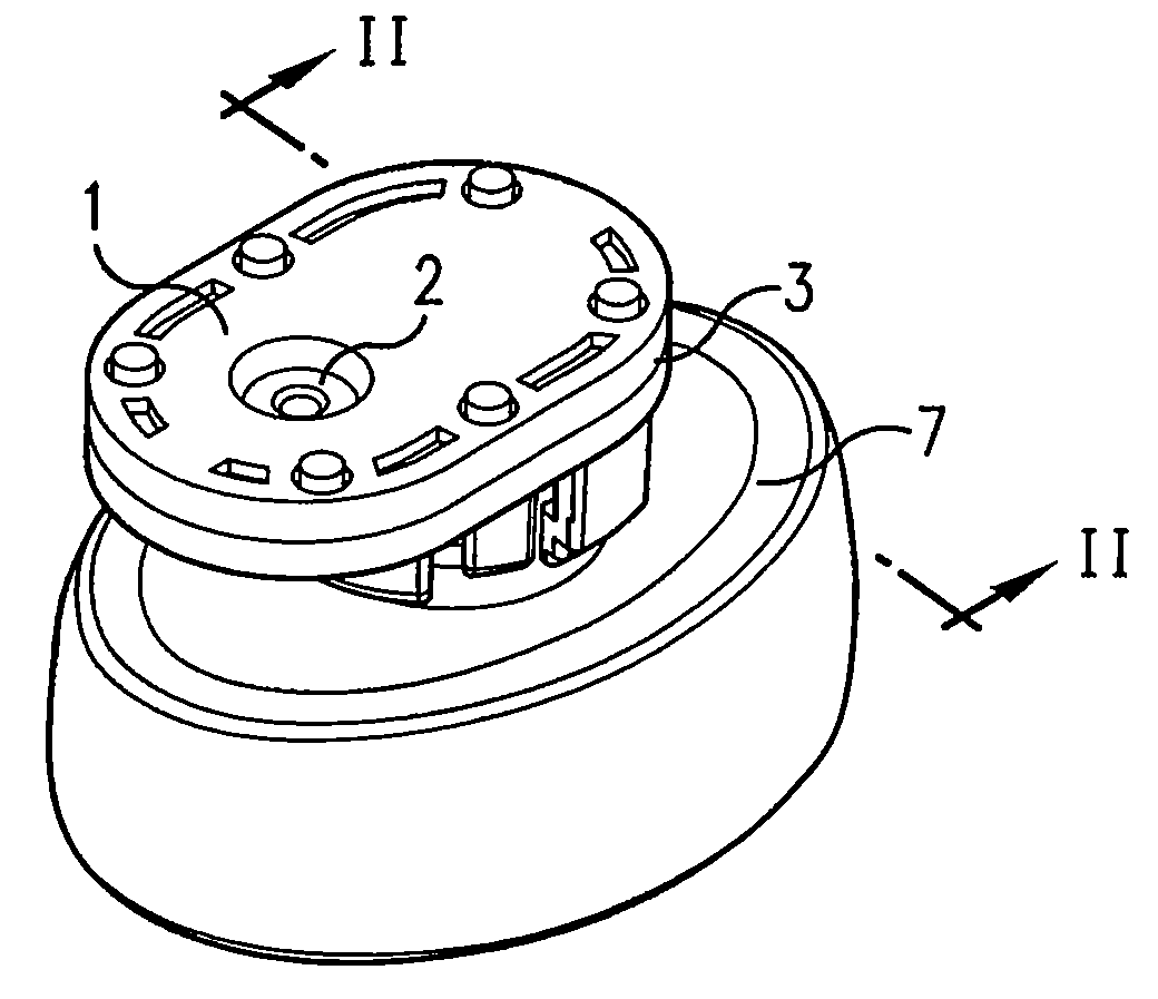
[0089]FIG. 1d shows an example of a second substrate 3, or the bottom packaging, which, together with the first substrate 1, forms the volatile liquid droplet dispenser device by assembling together these two substrates, i.e. by putting the top packaging onto the bottom packaging.

[0090]Second substrate 3 comprises connection means 3i for connection to a reservoir, also called a refill, containing a volatile liquid substance that is to be dispensed. In this case, connection means 3i may be of the screw-type having a partial inner thread for receiving the reservoir by twisting the latter into the partial thread, and may accommodate liquid inlet means provided in second substrate 3 for allowing the liquid substance to enter the volatile liquid droplet dispenser device from a reservoir. Such means are in themselves not inventive but may be a passive pump, for example a wick made a soft porous medium, that enters the reservoir to allow for extraction of the liquid into the device. Such ...

third embodiment

[0103]FIG. 2b shows a detailed view of another alternative arrangement of a nozzle membrane in a

[0104]In this embodiment, the priming channels are provided directly in the nozzle membrane 9.

[0105]These priming channels, referenced by 9a, are open towards space 2c, and have perforations constituting outlet nozzles 9b, as shown in FIGS. 2c and 2d.

[0106]Each priming channel 9a thus also functions as a capillary channel, because liquid that enters such channel will not seep out due to capillary constraints between the liquid and the sidewalls of the channels 9a.

[0107]The priming channels are provided directly in the nozzle membrane 9. Preferably, here too, each priming channel is open on its side proximate space 2c so as to receive the liquid substance from the space, and is perforated on its opposite side so as to constitute the outlet nozzles 9b of the perforated nozzle membrane. Thanks to these priming channels, it is possible to ensure presence of liquid in the immediate vicinity ...


PUM


Abstract

A volatile liquid droplet dispenser device includes: a first substrate (1) having a space (2c) for containing a liquid substance, and having liquid outlet means (2a) for ejecting the liquid substance; a second substrate (3) having a liquid inlet means (3i) for allowing the liquid substance to enter said device; an actuating element (2b, 8, 10) arranged to actuate the liquid substance so as to exit the device as a liquid droplet spray, wherein the liquid outlet means (2a) of the first substrate comprises a perforated nozzle membrane (2a) having a plurality of outlet nozzles, and wherein the first substrate (1) contains at least one fluidic capillary priming channel (1a, 1b, 1c) arranged to receive liquid substance from the space (2c) so as to fill the channel such that the liquid substance is in close proximity to the outlet nozzles for priming the liquid substance for ejection through the nozzle membrane.

Description

[0001]This application claims priority from European Patent Application No. 07 002 190.2, filed Feb. 1, 2007, the entire disclosure of which is incorporated herein by reference.FIELD OF THE INVENTION[0002]The present invention relates to a droplet dispensing device.BACKGROUND OF THE INVENTION[0003]Such droplet dispensing devices are also sometimes called aerosol generators, nebulizers and the like. They normally contain a nozzle body on a support part, in particular, a nozzle body of a liquid droplet spray device which dispenses a liquid substance as a liquid droplet spray or from the device through the nozzles of the nozzle body. They further consist of an actuator based on a vibrating element which generally causes the liquid to vibrate, to be accelerated and expelled as droplets. They further consist of elements such as liquid space, liquid feed and fluid interface to a reservoir, a reservoir as well as electrical connections between the vibrating element and a corresponding elec...

Claims


Application Information

Patent Timeline
Patent Type & Authority Applications(United States)
IPC IPC(8): B05B17/04B05B17/06B05B1/08F04B43/04
CPCB05B17/0684B05B17/0646
Inventor FERIANI, AMIRHESS, JOSEPH
Owner APTAR FRANCE SAS
Learn More