
Articulated arm assembly

a technology of articulating arms and arm parts, applied in the direction of drilling rods, drilling pipes, drilling casings, etc., can solve the problems of tripping hazards for rig crews, damage to drilling equipment, and routine and tedious work performed almost daily,

Inactive Publication Date: 2008-09-11
GE YAOGEN
View PDF2 Cites 18 Cited by
  • Summary
  • Abstract
  • Description
  • Claims
  • Application Information

AI Technical Summary

Benefits of technology

[0009]The invention of an articulated arm assembly described here is developed to carry a drilling related apparatus such as power tong, roughneck, drill sting, top drive, casing tong and any other applicable apparatus from the storage position to a working position such as well center or mouse hole. The preferred embodiment includes a combination of a pair of offset parallelograms and the dual compression support members, a column, a guide moving along the column. When a hydraulic cylinder or pneumatic cylinder mo

Problems solved by technology

In drilling industry, handling a drilling string is routine and tedious work performed almost on daily basis.
But it could be difficult to move such device on the rig due to unit heavy weight, limited space around the well center, which can cause accidents that could damage drilling apparatus and injure rig crew.
The problem with this configuration is that the floor mounted tracks often create tripping hazards for the rig crew.
It becomes difficult and usually complex when multiple locations are required to move the units.
It takes too much space on the rig.
It requires extra space and costly to manufacture, and also it is limited with the weight and size.
The problem of this type of device is difficult to position the unit because the weight of unit keeps the vertical position.
Moreover it is limited with relative short reach out.
The problems related to this device are that it has too many linkages and rotational elements that tend to wear and fail even, and that structurally the synchronized linkage as a main load path, becomes a weak link and easily wear and break.
It is costly to fabricate and difficult to service.
Many of these positioning device disclosed in the prior arts are generally having too many moving elements difficult to control, prone to wear and break.
All the devices lack self-holding function in case a hydraulic cylinder breaks, which can cause the tong or the roughneck to fall on the floor if that happens.

Method used


Image

  • Articulated arm assembly
  • Articulated arm assembly
  • Articulated arm assembly

Examples


Embodiment Construction

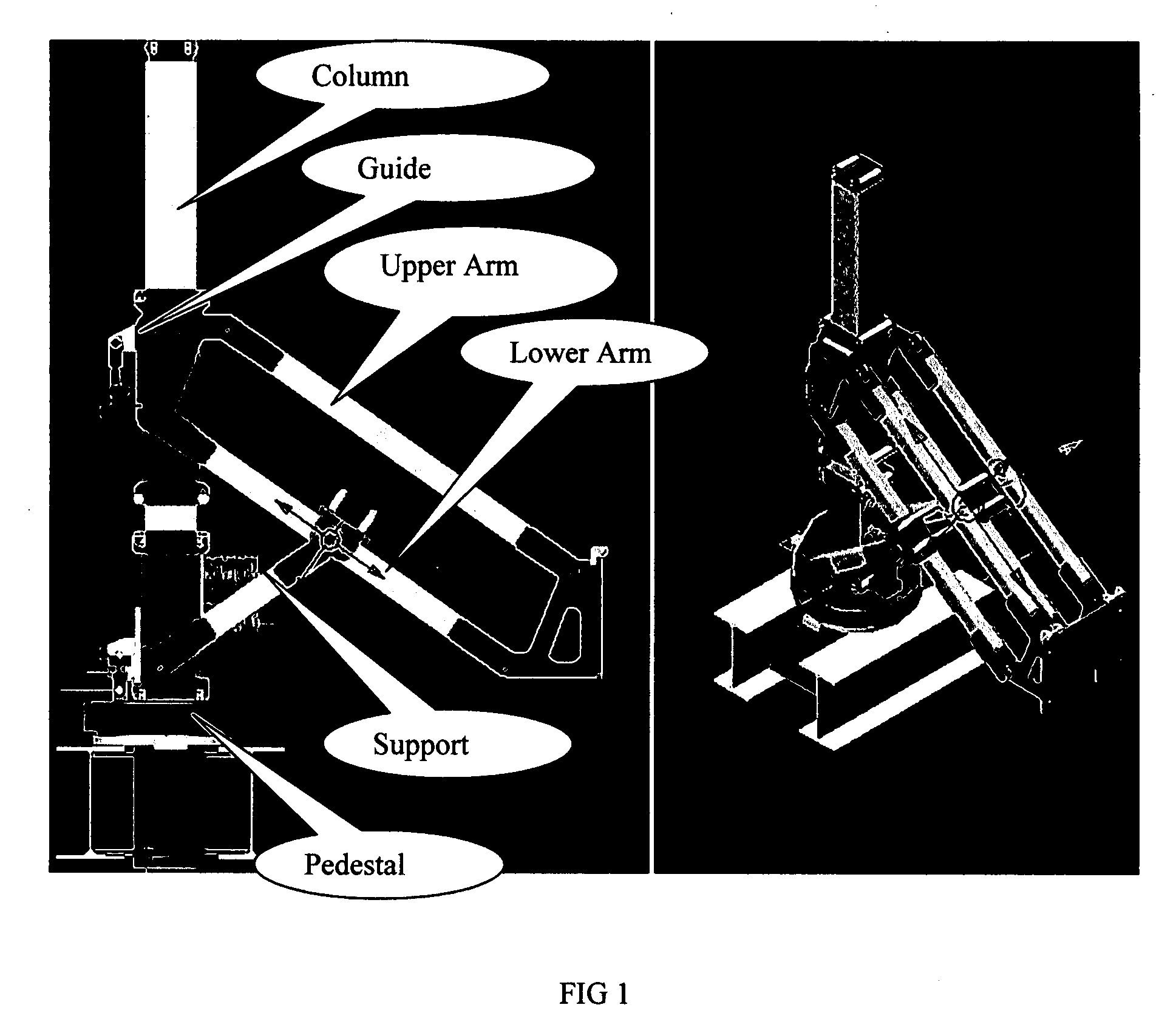
[0016]FIG. 1 is a 3d picture showing the preferred embodiment of the articulated arm assembly without showing a drilling apparatus attached the lower end of the parallelogram.

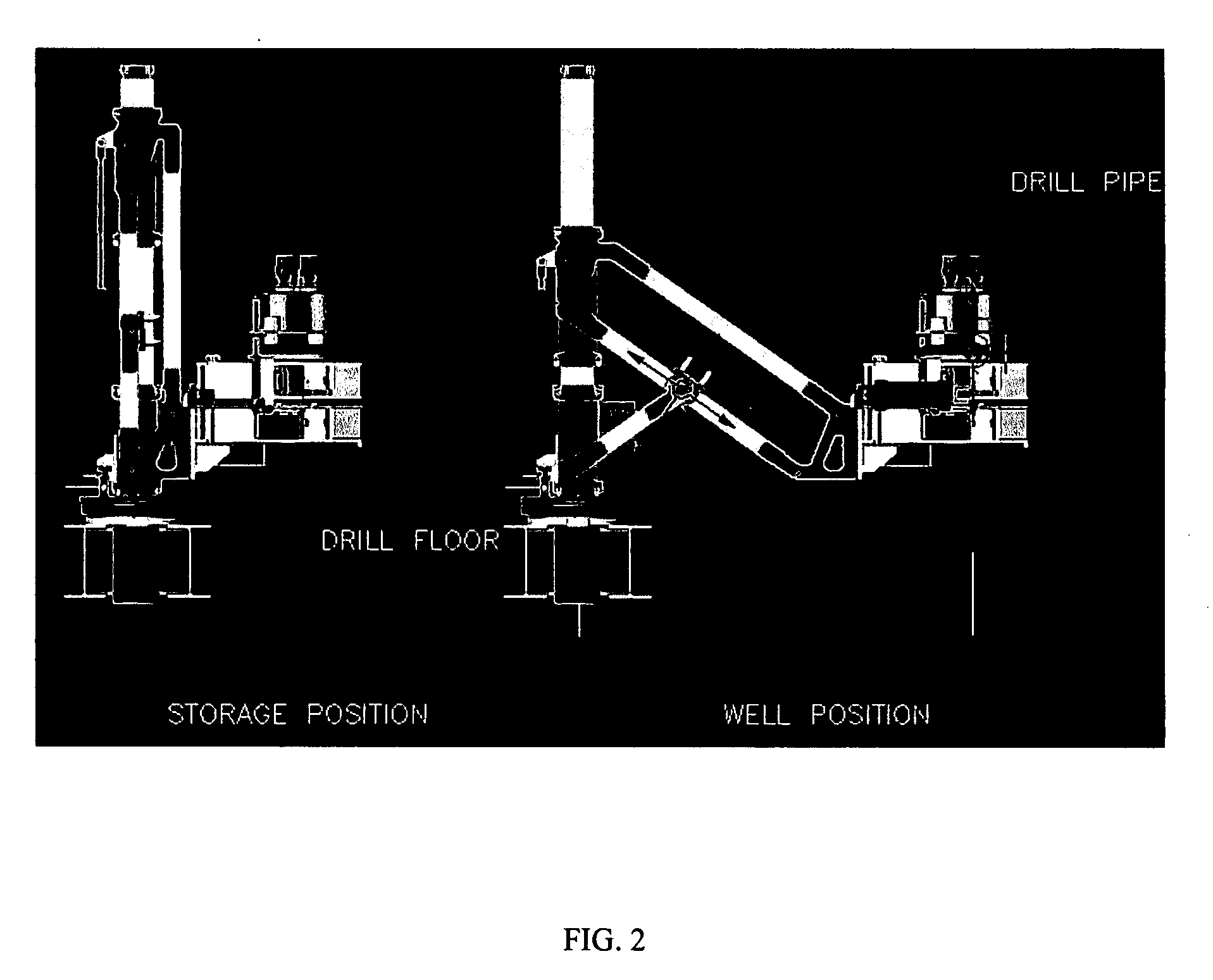
[0017]FIG. 2 is a typical arrangement of the articulated arm assembly with drilling apparatus such as a power tong attached to the lower end of the parallelogram. It shows the drilling apparatus is located in a storage position and travels to the well center by the articulated arm assembly.

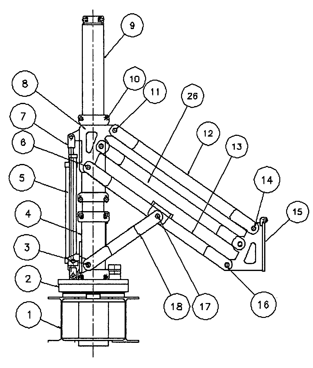
[0018]FIG. 3 is the configuration drawing of a preferred embodiment of this articulated arm assembly without showing a drilling apparatus or tool attached.

[0019]The arm assembly comprises at least one parallelogram which includes a upper member or linkage 12, lower member or linkage 13, a lower bracket 15, a upper linkage or the guide 8, wherein all the said members 12, 13 and the lower bracket 15 and the guide 8 are pivotally connected with pins.

[0020]The arm assembly further comprises a column 9, a pedestal 2 to support the...


PUM


Abstract

The invention of an articulated arm assembly described here is to carry and position a drilling related apparatus such as power tong, roughneck, drill sting, top drive, casing tong and any other applicable apparatus from the storage position to a working position such as well center or mouse hole. The combination of a parallelogram, a support arm, and a movable guide provides a simple means to move and position a drilling apparatus between a storage position to a desired working position such as a well center and to maintain the drilling apparatus at any desired position.

Description

FIELD OF INVENTION[0001]The present invention is used to carry and position a drilling apparatus in oil and gas industry. In particular, the invention of an articulated arm assembly described here is to carry and position a drilling related apparatus such as power tong, roughneck, drill sting, top drive, casing tong and any other applicable apparatus from the storage position to a working position such as well center or mouse hole with a means of safer, more efficient and reliable, and also less risk for rig crew to hand the drill string during drilling operation.BACKGROUND OF THE INVENTION[0002]In drilling industry, handling a drilling string is routine and tedious work performed almost on daily basis. The apparatus normally called power tong or roughneck is often utilized to make or break the threaded tool joint connection of a drilling string.[0003]It is necessary to move the power tong or the roughneck between various locations including well center, mouse hole and a storage pos...

Claims


Application Information

Patent Timeline
IPC IPC(8): E21B19/00
CPCE21B19/00
Inventor GE, YAOGEN
Owner GE YAOGEN
Learn More