
Vibration assembly, input device using the vibration assembly, and electronic equipment using the input device

a technology of vibration assembly and input device, which is applied in the direction of mechanical vibration separation, instruments, specific gravity measurement, etc., can solve the problems of increasing cost, difficulty in applying the speaker for the ringtone melody or the like,

Inactive Publication Date: 2008-09-11
THOMSON LICENSING SA
View PDF9 Cites 76 Cited by
  • Summary
  • Abstract
  • Description
  • Claims
  • Application Information

AI Technical Summary

Benefits of technology

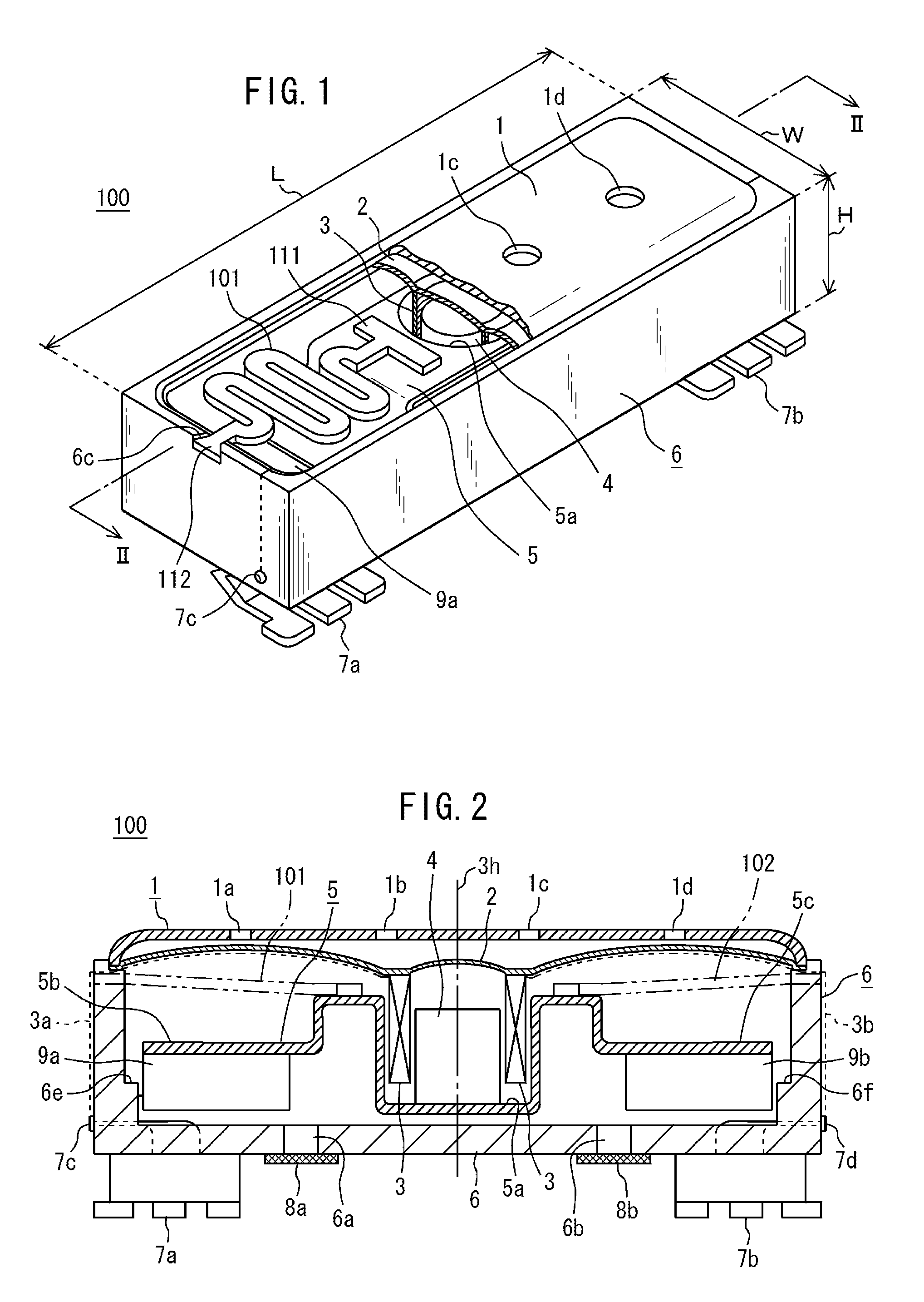
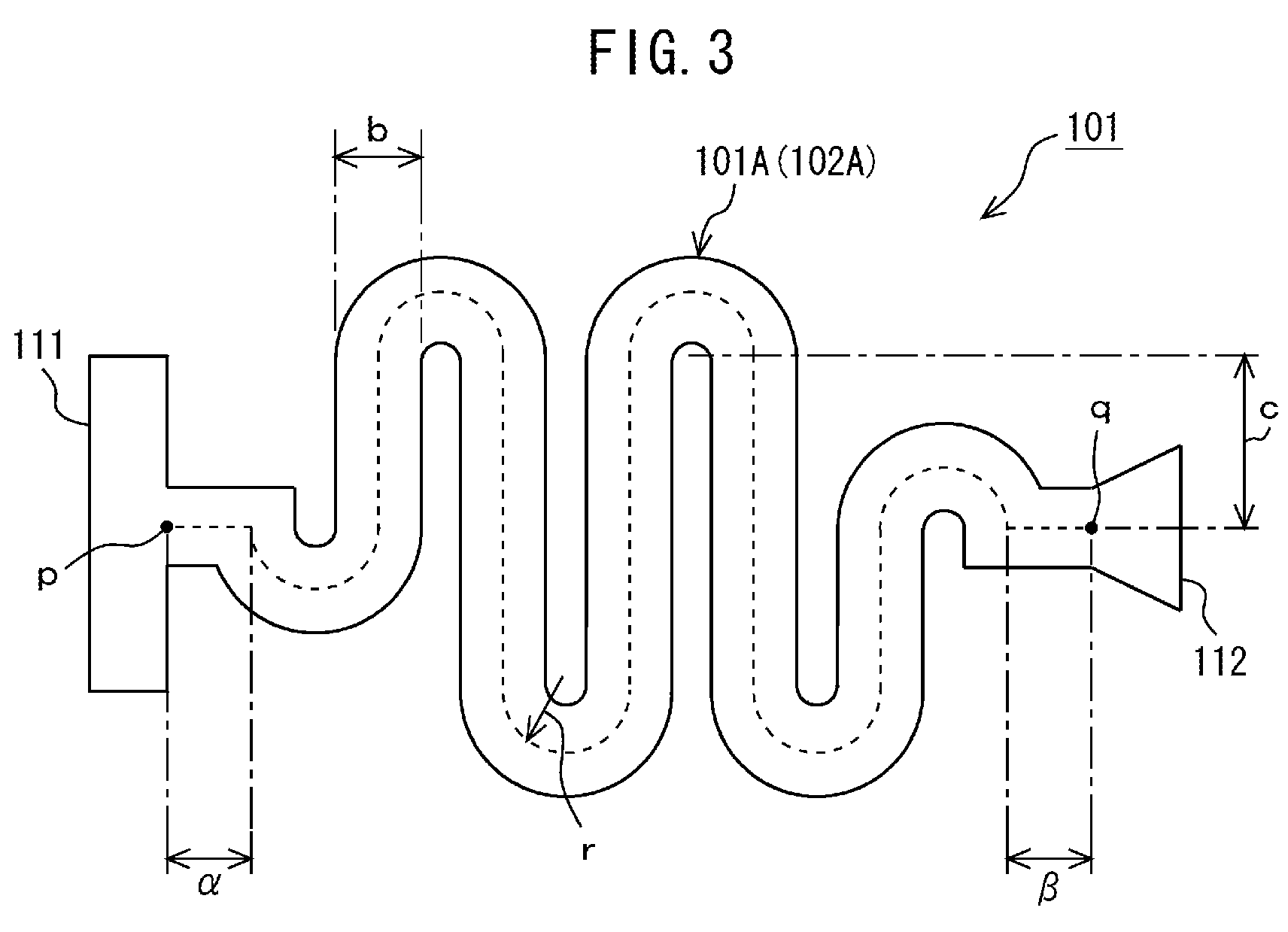
[0016]The vibration assembly according to an embodiment of the present invention vibrates the diaphragm to act as a speaker when applying an audio signal to the coil movably positioned around the magnetic body. Alternatively, by the vibration assembly according to an embodiment of the present invention, when applying a low frequency signal for feedback of a vibration to a user to the coil, the vibration member vibrates based on the resonance frequency given by the expression that is in inverse proportion to a square root of the cube of the length of the support member having a flat and corrugated configuration and is in proportion to a square root of the cube of the thickness of the support member. This enables the feedback of a vibration to a user to be performed. Further, the support members convert a direction of a vibration generated along the spool axis of the coil to a direction perpendicular to the spool axis of the coil. Such the configuration allows the vibration assembly to be downsized.
[0017]Thus, according to the embodiment of the present invention, it is capable of providing a very small size vibration assembly with speaker function.
[0020]Alternatively, by the embodiment of the input device according to the present invention, when applying a low frequency signal for feedback of a vibration to a user to the coil based on the user's manipulation on the input-detecting unit, the vibration member vibrates based on the resonance frequency given by the expression that is in inverse proportion to a square root of the cube of the length of the support member having a flat and corrugated configuration and is in proportion to a square root of the cube of the thickness of the support member. This enables the feedback of a vibration to be presented to a user.
[0021]Such the input device can have both of receiver function and actuator function. This results in reduction in its costs.
[0024]Alternatively, by the embodiment of the electronic assembly according to the present invention, when applying a low frequency signal for feedback of a vibration to a user to the coil based on the user's manipulation on the input-detecting unit, the vibration member vibrates based on the resonance frequency given by the expression that is in inverse proportion to a square root of the cube of the length of the support member having a flat and corrugated configuration and is in proportion to a square root of the cube of the thickness of the support member. This enables the feedback of a vibration to be presented to a user.
[0025]Such the electronic equipment contains the vibration assembly that also serves as the vibrator and the receiver, so that the electronic equipment can be downsized.

Problems solved by technology

It is thus difficult to apply the speaker for the ringtone melody or the like to the upper casing equipped with the display monitor as an actuator for feedback of the vibration to the user by the user's sense of touch.
Even if applying the speaker for the ringtone melody or the like to the upper casing equipped with the display monitor as an actuator for feedback of the vibration to the user by the user's sense of touch, the mobile phone may have a larger section or result in an increase in cost.

Method used


Image

  • Vibration assembly, input device using the vibration assembly, and electronic equipment using the input device
  • Vibration assembly, input device using the vibration assembly, and electronic equipment using the input device
  • Vibration assembly, input device using the vibration assembly, and electronic equipment using the input device

Examples


Embodiment Construction

[0042]The following will describe embodiments of a vibration assembly, input device, and electronic equipment according to the present invention with reference to the accompanied drawings.

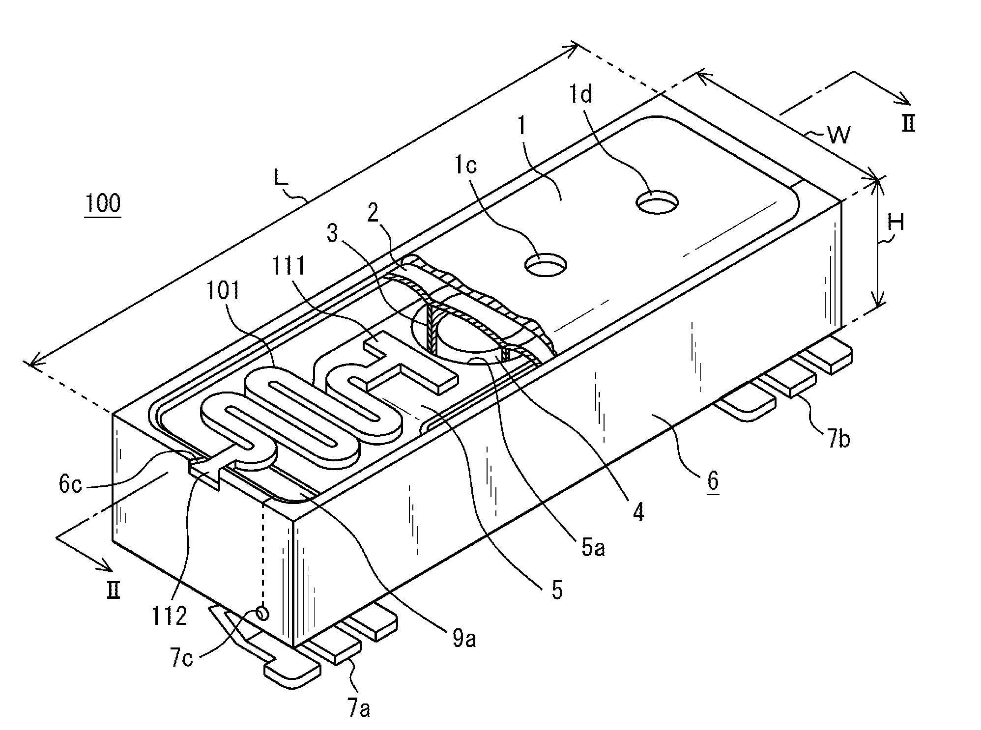
[0043]FIG. 1 illustrates a configuration of a very small size speaker 100 with an actuator function, to which an embodiment of a vibration assembly according to the invention is applicable. FIG. 2 is a cross sectional view of the speaker 100.

[0044]The speaker 100 has both of a speaker function and an actuator function that generates any vibration for user's sense of touch. The speaker 100 is applicable to any electronic equipment such as an information-processing device, a mobile phone, and a PDA, which presents feedback of a vibration to a user by the user's sense of touch when the user input any information by selecting an item from input selection items displayed on a screen by an icon.

[0045]The speaker 100 has a housing 6 constituting a container and a lid 1 that is attached on the housing 6 af...


PUM


Abstract

A vibration assembly includes a container, a vibration member containing a hollow portion with a bottom, at least two support members, a magnetic body, a coil having a spool axis, and a diaphragm that is attached to the container. Each of the support members has a flat and corrugated configuration. An end of the one of the support members is bonded to a portion of an edge portion of the hollow portion of the vibration member. The other end of the one of the support members is fixed to a portion of an upper edge of the container. An end of the other support member is bonded to the other portion of the edge portion of the hollow portion of the vibration member. The other end of the other support member is fixed to the other portion of the upper edge of the container.

Description

CROSS-REFERENCES TO RELATED APPLICATIONS[0001]The present invention contains subject matter related to Japanese Patent Application JP 2007-060787 filed in the Japanese Patent Office on Mar. 9, 2007, the entire contents of which being incorporated herein by reference.BACKGROUND OF THE INVENTION[0002]1. Field of the Invention[0003]The present invention relates to a vibration assembly, input device containing the vibration assembly, which can realizes feedback of a vibration to a user by the user's sense of touch, and electronic equipment such as an information-processing device, a mobile phone, and a personal digital assistant (PDA), which contains the input device.[0004]2. Description of Related Art[0005]User has recently captured various kinds of contents on electronic equipment such as an information-processing device, a mobile telephone, and a PDA and utilized the contents. The electronic equipment has any input device. The input device contains a key board and a jog dial, and a t...

Claims


Application Information

Patent Timeline
IPC IPC(8): G01N29/00G01N33/00G06F3/037G06F3/041
CPCB06B1/045G06F3/016G06F3/0414H04R2499/11G06F2203/014H04R9/06G06F3/0488
Inventor TAKASHIMA, KOUICHIROKAYAMA, SHUNTAKAHASHI, TSUTOMUSHIMIZU, YUKIKOOKII, HIDEKISAWADA, TAKASHI
Owner THOMSON LICENSING SA
Learn More