
Method and device for mounting of wind turbine blades

a technology for wind turbine blades and mounting devices, which is applied in the manufacture of machines/engines, manufacturing tools, and final products. it can solve the problems of increasing difficulty in assembling the wind turbine rotor on the ground, complicated lifting of the rotor to the nacelle, and increasing difficulty

Active Publication Date: 2008-09-11
SIEMENS GAMESA RENEWABLE ENERGY AS
View PDF6 Cites 77 Cited by
  • Summary
  • Abstract
  • Description
  • Claims
  • Application Information

AI Technical Summary

Benefits of technology

[0008]It is therefore an objective of the present invention to provide an advantageous method for lifting a wind turbine blade to a wind turbine hub. It is a further objective to provide an advantageous wind turbine blade lifting system.

Problems solved by technology

The usual way of mounting a wind turbine comprises a number of drawbacks which have become more and more severe with the increasing size and width of the wind turbine rotor.
Assembling the wind turbine rotor on the ground is especially difficult as it requires a large area free of obstacles which is substantially horizontal and stable in order to be accessible for the assembly workers and the crane.
Furthermore, lifting the rotor to the nacelle is rather complicated as the rotor must be turned by 90° in midair.
However, in this lifting system the blade has to be vertical during lifting and mounting.
This means that, as a part of the lifting process, the blade has to be turned and during the positioning of the blade there is little control over the angular blade orientation.
However, any wind occurring at the time of lifting will tend to deflect the blade.
For large blades and tall towers the control of such steering becomes a major challenge.

Method used


Image

  • Method and device for mounting of wind turbine blades
  • Method and device for mounting of wind turbine blades
  • Method and device for mounting of wind turbine blades

Examples


Embodiment Construction

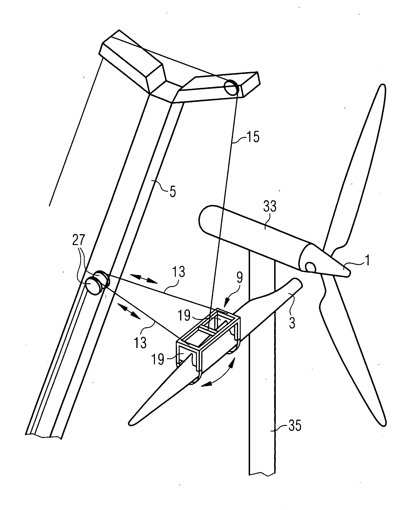
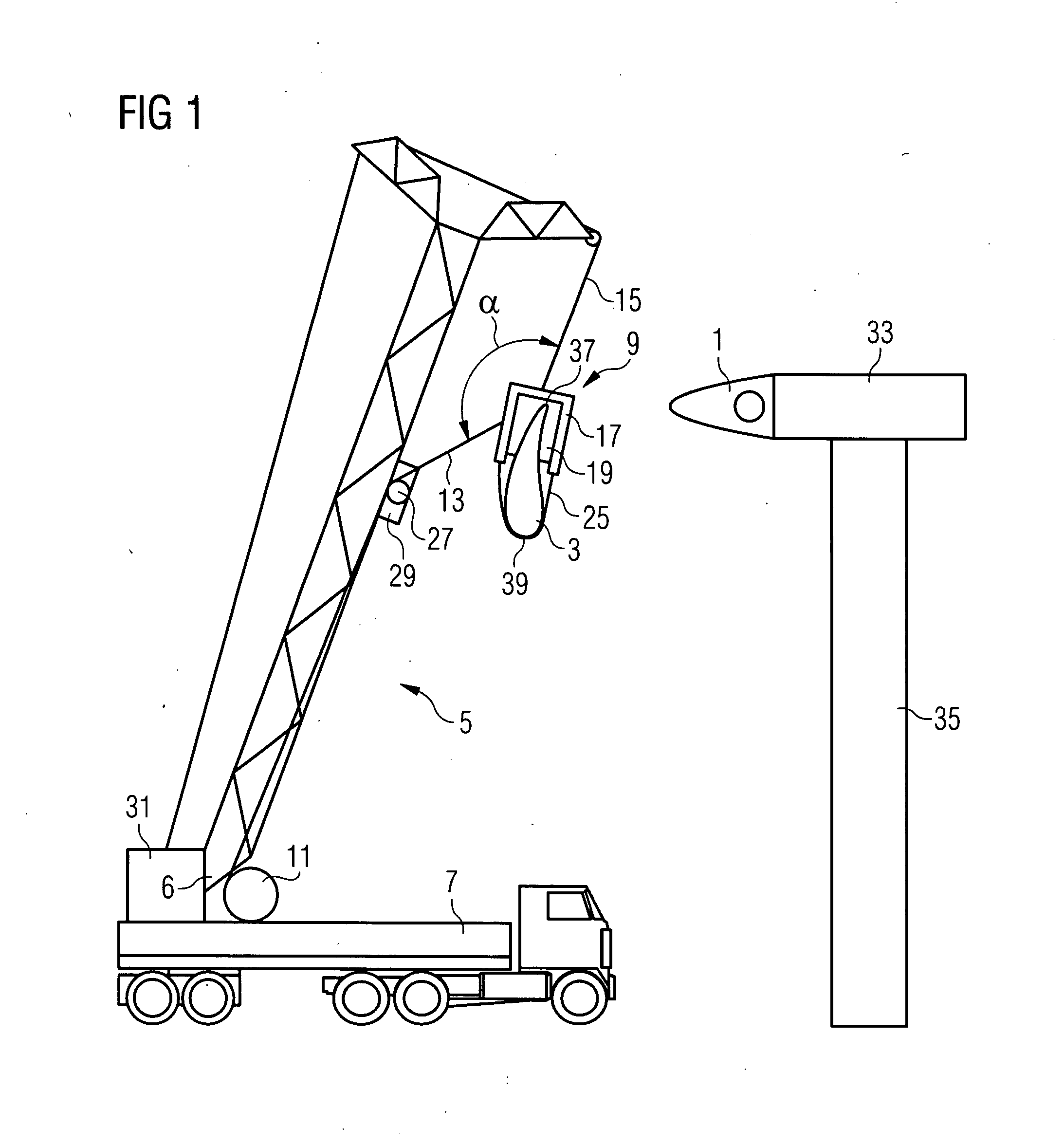
[0024]An inventive wind turbine blade lifting system will now be described with respect to FIGS. 1 and 2. While FIG. 1 shows the lifting system in a view onto the tip of the lifted turbine blade, FIG. 2 shows the upper part of the wind turbine blade lifting system in a plan view onto the blade's body. Also shown in both figures is the rotor hub 1 onto which the blade 3 is to be mounted. It is located at a nacelle 33 at the top of a tower 35.

[0025]The wind turbine blade lifting system comprises a crane boom 5 which is mounted onto a truck 7, a lifting device 9 which can be connected to the wind turbine blade 3, a winch arrangement comprising two individually controllable winches 11, control wires 13 (only one control wire is visible in FIG. 1) and a bearing wire 15.

[0026]The holding device 9 comprises a frame 17 and seats 19 on both ends 21, 23 of the frame 17 to which the wind turbine blade 3 is pressed by belts or straps 25. In addition, the bearing wire 15 is fixed to a central ar...


PUM

PropertyMeasurementUnit
Weightaaaaaaaaaa

Abstract

A method for mounting a wind turbine blade to a wind turbine hub by use of a crane boom is provided. The orientation of the blade is kept substantially horizontal when the blade is lifted off the ground and mounted to the rotor hub. Control wires which connect the blade via the crane boom to a winch arrangement are used for keeping the blade orientation substantially horizontal in addition to at least one bearing wire for bearing the blade weight.

Description

CROSS REFERENCE TO RELATED APPLICATIONS[0001]This application claims priority of European Patent Office application No. 06024336.7 EP filed Nov. 23, 2006, European Patent Office application No. 06024337.5 EP filed Nov. 23, 2006, and European Patent Office application No. 07013724 EP filed Jul. 12, 2007, all of the applications are incorporated by reference herein in their entirety.FIELD OF INVENTION[0002]In general, the invention relates to methods of handling wind turbine blades and mounting said blades on a wind turbine and a system and gripping unit for handling a wind turbine blade. In particular, the present invention relates to a method of mounting wind turbine blades to a rotor hub wherein the orientation of the blades is kept substantially horizontal when the blade is lifted off the ground. In addition, the present invention relates to a wind turbine blade lifting system which is particularly suitable for performing the inventive method.BACKGROUND OF INVENTION[0003]Modern wi...

Claims


Application Information

Patent Timeline
IPC IPC(8): B23P19/00B66C13/04B66C23/18B23P15/04
CPCB66C1/108B66C23/185B66C23/36F03D1/001F03D11/04F05B2230/61Y10T29/49826Y02E10/726Y02E10/728Y02E10/721B66C1/42B66C13/08Y10T29/49316F05B2250/30F03D13/20F03D13/10F03D13/40Y02E10/72Y02P70/50
Inventor HANSEN, HENRIK LYNDERUPMOELLER, JESPER
Owner SIEMENS GAMESA RENEWABLE ENERGY AS
Learn More