
Remote monitoring system

Inactive Publication Date: 2008-09-04
AMERICA POWER CONVERSION CORP
View PDF100 Cites 64 Cited by
  • Summary
  • Abstract
  • Description
  • Claims
  • Application Information

AI Technical Summary

Benefits of technology

[0009]Characteristics of the invention may include one or more of the following capabilities. A monitoring center can provide a human interface for analyzing and reporting data related to devices at remote locations. Customers can be directly contacted via phone, email or other means upon severe event occurrence. Service start-up of devices is monitored by the remote monitoring center. Device registration can be performed automatically in response to device purchase. Outsourcing for management of tickets, contracts / agreements or bulletin board notices may be alleviated. Data may be analyzed to determine maintenance needs. Implementation of additional remote monitoring devices at the site of electronic devices is avoided. Troubleshooting can be accomplished via a service center and can occur at the time of event occurrence. Devices can be controlled via the remote monitoring service to alter operations when events occur. Manpower for monitoring internal systems at the customer site and cost related thereto can be reduced.

Problems solved by technology

Without power, companies may be unable to manufacture goods, or to operate at all, such as if the company is in the business of supplying information over the Internet.
Without power, businesses and individuals may be completely incapacitated regarding critical activities, such as making goods, providing services, and transacting personal finances (e.g., filing tax returns, and paying bills).

Method used


Image

  • Remote monitoring system
  • Remote monitoring system
  • Remote monitoring system

Examples


Embodiment Construction

[0042]This invention is not limited in its application to the details of construction and the arrangement of components set forth in the following description or illustrated in the drawings. The invention is capable of other embodiments and of being practiced or of being carried out in various ways. Also, the phraseology and terminology used herein is for the purpose of description and should not be regarded as limiting. The use of “including,”“comprising,” or “having,”“containing”, “involving”, and variations thereof herein, is meant to encompass the items listed thereafter and equivalents thereof as well as additional items.

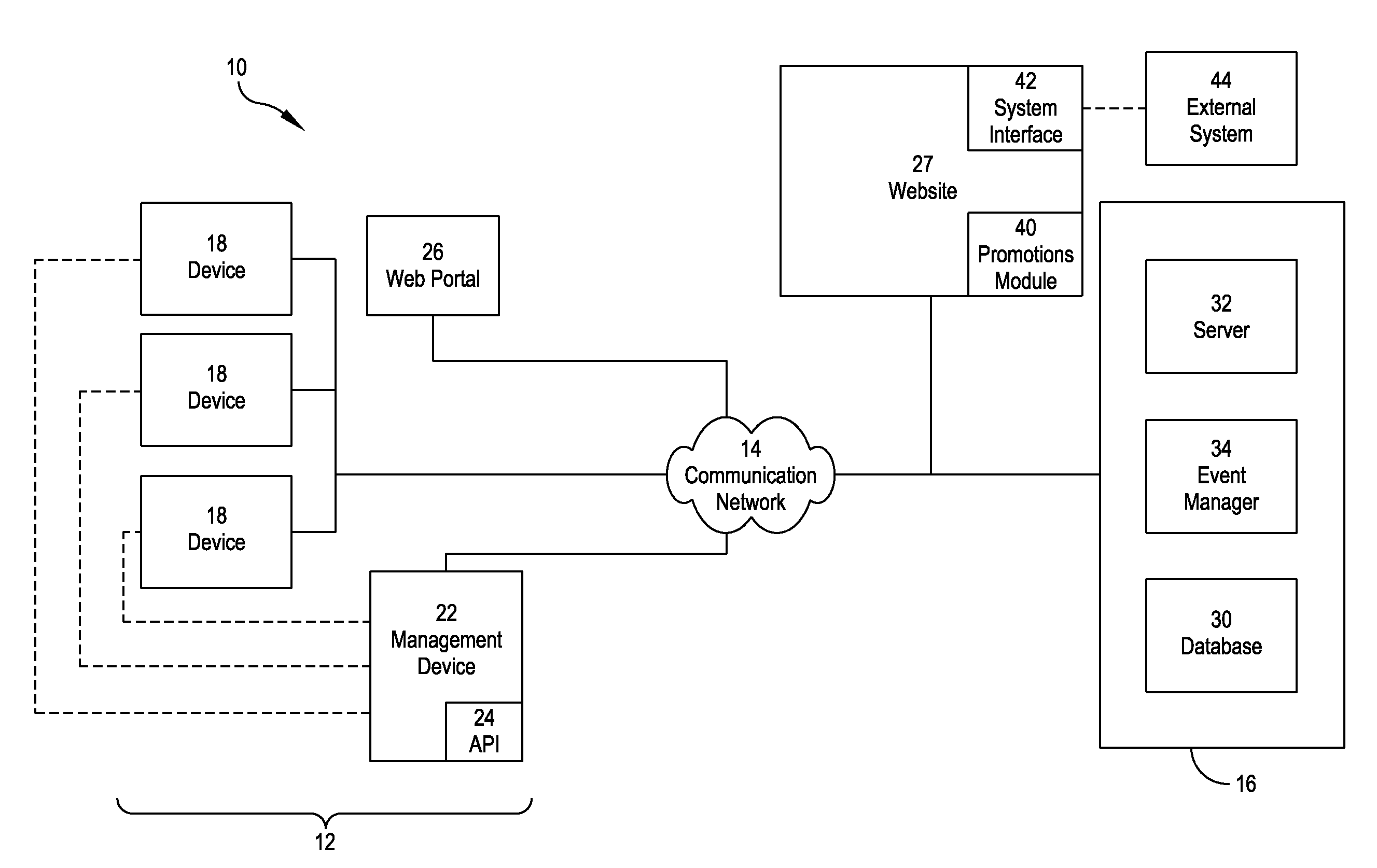
[0043]Various embodiments of the present invention provide techniques for monitoring devices from a remote location. Also, various aspects of the present invention relate to reporting the status of devices and controlling devices from the remote location. According to one embodiment, devices can be monitored at distributed locations, reported to a centralized m...


PUM


Abstract

A method for monitoring and reporting information regarding status of a power supply / management device operated by a user comprises detecting the status of the device using a monitoring device having an application interface configured to communicate over a communication network, generating a status update indication using a self-describing computer language and sending the status update indication over the communication network to a remote computer, and associating the user with the status update information for the remote device using the remote computer.

Description

RELATED APPLICATIONS[0001]This application claims priority under 35 U.S.C. § 119(e) to U.S. Provisional Application Ser. No. 60 / 893,772, entitled “REMOTE MONITORING SYSTEM,” filed on Mar. 8, 2007 and is a continuation in part of U.S. application Ser. No. 11 / 302,578, entitled “REMOTE MONITORING SYSTEM,” filed on Dec. 13, 2005, which claims priority under 35 U.S.C. § 119(e) to U.S. Provisional Application Ser. No. 60 / 635,797, entitled “REMOTE MONITORING SYSTEM,” filed on Dec. 13, 2004. Each of these applications is herein incorporated by reference in its entirety.BACKGROUND OF INVENTION[0002]Today, companies and persons rely on having consistent supply of power to electronic devices more than ever. Without power, companies may be unable to manufacture goods, or to operate at all, such as if the company is in the business of supplying information over the Internet. Without power, businesses and individuals may be completely incapacitated regarding critical activities, such as making go...

Claims


Application Information

Patent Timeline
IPC IPC(8): G06F15/173G06F15/16G06F7/06G06F17/30
CPCH04L41/06H04L41/147H04L43/106H04L43/0817H04L43/06
Inventor DENIS, ARNAUDPOLITTE, MAUREENCALABIO, RANDYNGUYEN, HOAI
Owner AMERICA POWER CONVERSION CORP
Learn More