Directional stimulation of neural tissue

Active Publication Date: 2008-09-04
ALPHA OMEGA NEURO TECH
View PDF12 Cites 202 Cited by
  • Summary
  • Abstract
  • Description
  • Claims
  • Application Information

AI Technical Summary

Benefits of technology

[0014]In an exemplary embodiment of the invention, anodal fields are used to limit the extent of the stimulation area. In an exemplary embodiment of the invention, cathodal spread is stopped after 5-10 mm. These distances may be useful for reducing the induction of side effects during stimulation.
[0021]In another embodiment, there is no anode dedicated to the shielding. Instead, the stimulating electrodes on the first lead are electrified such that some of them are anodes and some of them are cathodes, with higher currents loaded on the anodes, so that from a relatively distant point, the total effect is that of an anode. The excess anodal currents created this way are collected by the cathode of the second lead (or a distant electrode or an IPG case), and create anodal shielding.
[0027]It has been found by the inventors, that making one, some, or all of the electrode contacts with internal edges may add to the flexibility in defining the shape of the electrical field provided by leads or systems according to some embodiments of the invention. In the present application, the term internal edge is used to refer to any feature that results in non-uniform electrical properties throughout the contact surface facing the tissue. Examples to electrical properties that are non-uniform include impedance per surface area, and current flux. In this context, internal edge is a structural feature that behaves electrically as an edge, but is not at the edge of the contact, but rather on an internal part thereof. Optionally, an internal edge comprises a plurality of mini internal edges. Optionally, the plurality of mini internal edges has a uniform density. Alternatively, the mini internal edges are disposed to create regions of different mini edge densities. For example, an internal edge may comprise several mini internal edges, the concentration profile of which has a maximum at the center of the internal edge.
[0088]evaluating said quality using a method according to claim 36; and thereafter, without displacing the electrode contact in relation to the examining contacts, electrically etching said electrode contact so as to improve said quality.

Problems solved by technology

However, the applied stimulation might also affect tissue at the proximity of the region of interest, and such stimulation might cause unwanted side-effects.

Method used


Image

  • Directional stimulation of neural tissue
  • Directional stimulation of neural tissue
  • Directional stimulation of neural tissue

Examples


Embodiment Construction

[0227]overview

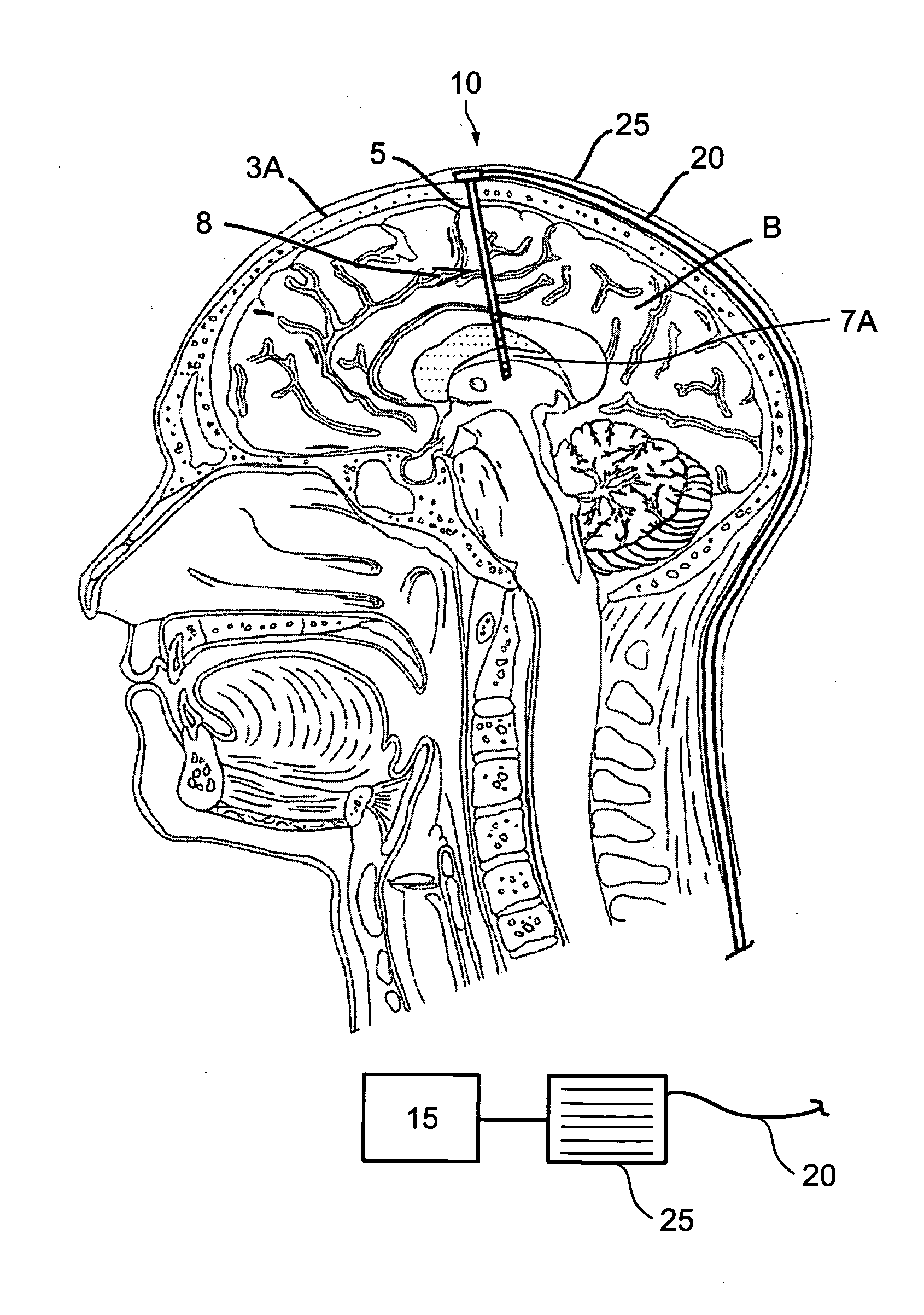
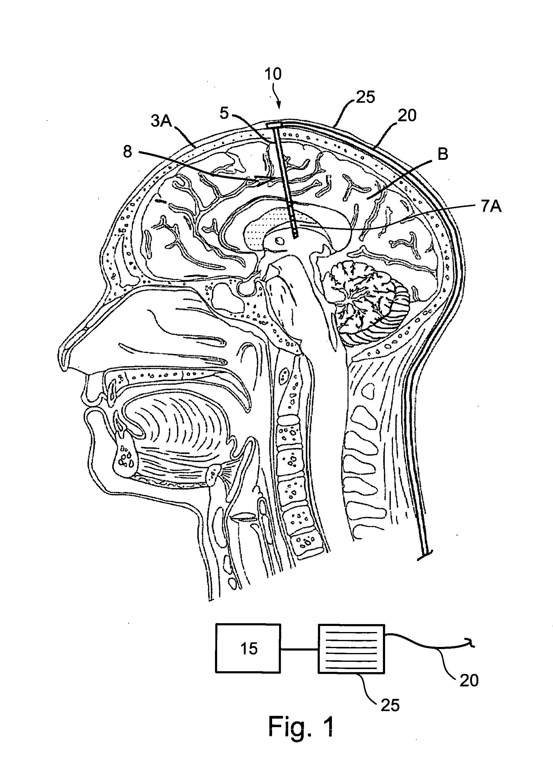
[0228]A lead according to various embodiments of the invention may be leaded in a brain for supplying therapeutic neural stimulation. FIG. 1 is a cross-sectional view of a brain (B) showing a lead (5) placed in the brain according to an embodiment of the invention. Lead 5 has a distal portion (7) a proximal portion (10), and an intermediate portion (8) between them.

[0229]Distal portion 7 of lead 5 is leaded in brain B through a hole in the skull. Distal portion 7 has electrode contacts 7A for providing electrical stimulation to the brain. Such contacts are described in more detail below. In other embodiments of the invention, the electrode contacts may be in other parts of the lead, such as in a proximal portion or in an intermediate portion, all depending on the direction at which the lead is inserted into the tissue. Nevertheless, for simplicity of presentation, the following description uses terminology suitable for a lead inserted as shown in FIG. 1. A skilled pers...


PUM


Abstract

A multi-contact electrode for neural tissue stimulation is described. The electrode has an axis and includes a plurality of electrodes going along the axis. Each electrode ends with a contact, and at least one of the contacts has an internal edge, resulting in non-uniform electrical properties throughout the contact surface facing the tissue. Also described are methods of making an electrical contact with an internal edge, and methods and systems for characterizing internal edge.

Description

RELATED APPLICATIONS[0001]This application claims the benefit under 119(e) of U.S. Provisional Patent Applications No. 60 / 903,533 and 60 / 903,537 both filed on Feb. 27, 2007.[0002]This application is also a continuation-in-part (CIP) of PCT Patent Application No. PCT / IL2007 / 000983, filed on Aug. 7, 2007, which claims the benefit of U.S. Provisional Patent Applications No. 60 / 903,533 and 60 / 903,537, both filed on Feb. 27, 2007, 60 / 849,468 filed on Oct. 5, 2006; 60 / 835,881 filed on Aug. 7, 2006; 60 / 835,890 filed on Aug. 7, 2006; 60 / 835,891 filed on Aug. 7, 2006; and 60 / 835,902 filed on Aug. 7, 2006.[0003]The contents of each of the above applications are incorporated herein by reference.FIELD OF THE INVENTION[0004]The present invention relates to electrodes for stimulating tissue at a region of interest and to a method of operating such electrodes.BACKGROUND OF THE INVENTION[0005]Electric stimulation of neural tissue is used to treat a variety of disorders. Specifically, leadable elect...

Claims


Application Information

Patent Timeline
IPC IPC(8): A61N1/04
CPCA61N1/36082A61N1/0534
Inventor FARAH, MAROUNYOUNIS, IMAD
Owner ALPHA OMEGA NEURO TECH
Why Eureka
Try Eureka