Eureka AIR delivers breakthrough ideas for toughest innovation challenges, trusted by R&D personnel around the world.

Rotary Device for Transferring Containers

a rotary device and container technology, applied in the direction of mechanical conveyors, conveyor parts, transportation and packaging, etc., can solve the problems of increasing the volume of the conveyor device, increasing the difficulty of manufacturing and requiring space, and generating vibration and noise, so as to reduce the number of cams, reduce the number of components, and simplify the structure

Inactive Publication Date: 2008-09-04
SIDEL PARTICIPATIONS SAS
View PDF8 Cites 18 Cited by
  • Summary
  • Abstract
  • Description
  • Claims
  • Application Information

AI Technical Summary

Benefits of technology

The invention is a conveyor device for manufacturing containers that has a simplified structure, fewer components, and higher operating speeds. It is designed to provide a better transfer arm that can deliver preforms or gripping finished containers by accompanying the mold through a given angular sector. The device has a pivot shaft and a free end of the main arm that define a line that extends approximately tangentially to the pivot shaft. The curvilinear cam is designed to move the gripping pincer in a predetermined circular path, and the gripping pincer follows a trajectory that is opposite to the rotary base. The transfer arm is designed in a way that sliding members and moving members are reduced, and the capacity of movement is increased. The device can operate at higher speeds and is cost-effective.

Problems solved by technology

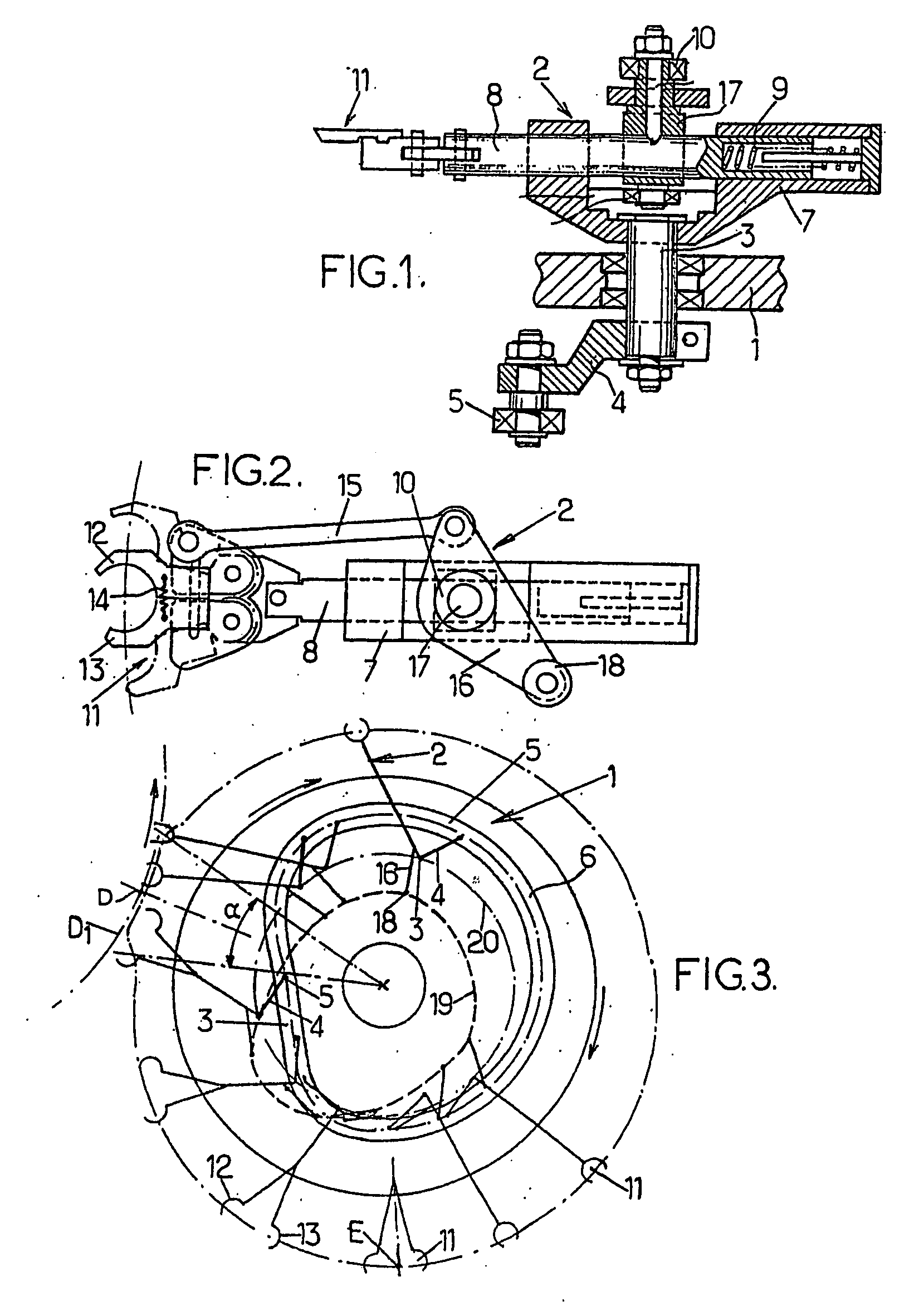
However, these arrangements are structurally complex, using, for example, sliding members as part of the structure of the telescopic arms, which generate friction and consequently wear; this results in the progressive development of play which generates vibration and noise.
Furthermore, the multiple movements of moving parts require the installation of corresponding cams, which are difficult to manufacture and require an amount of space according to their number.
Above all, the conveyor device designed as described above has a large transverse dimension, and the overall bulk of the conveyor device is even more troublesome because the bulk of the devices located at the entrance of the molding device projects from the unit formed by the installation as a whole.
Finally, the multiplicity of the members and the multiplicity of the movements are such that it is impossible to attempt to make the known conveyor device operate at higher speeds than those currently used, even though there is a strong demand for higher output rates among the users of container manufacturing installations.

Method used


Image

  • Rotary Device for Transferring Containers
  • Rotary Device for Transferring Containers
  • Rotary Device for Transferring Containers

Examples


Embodiment Construction

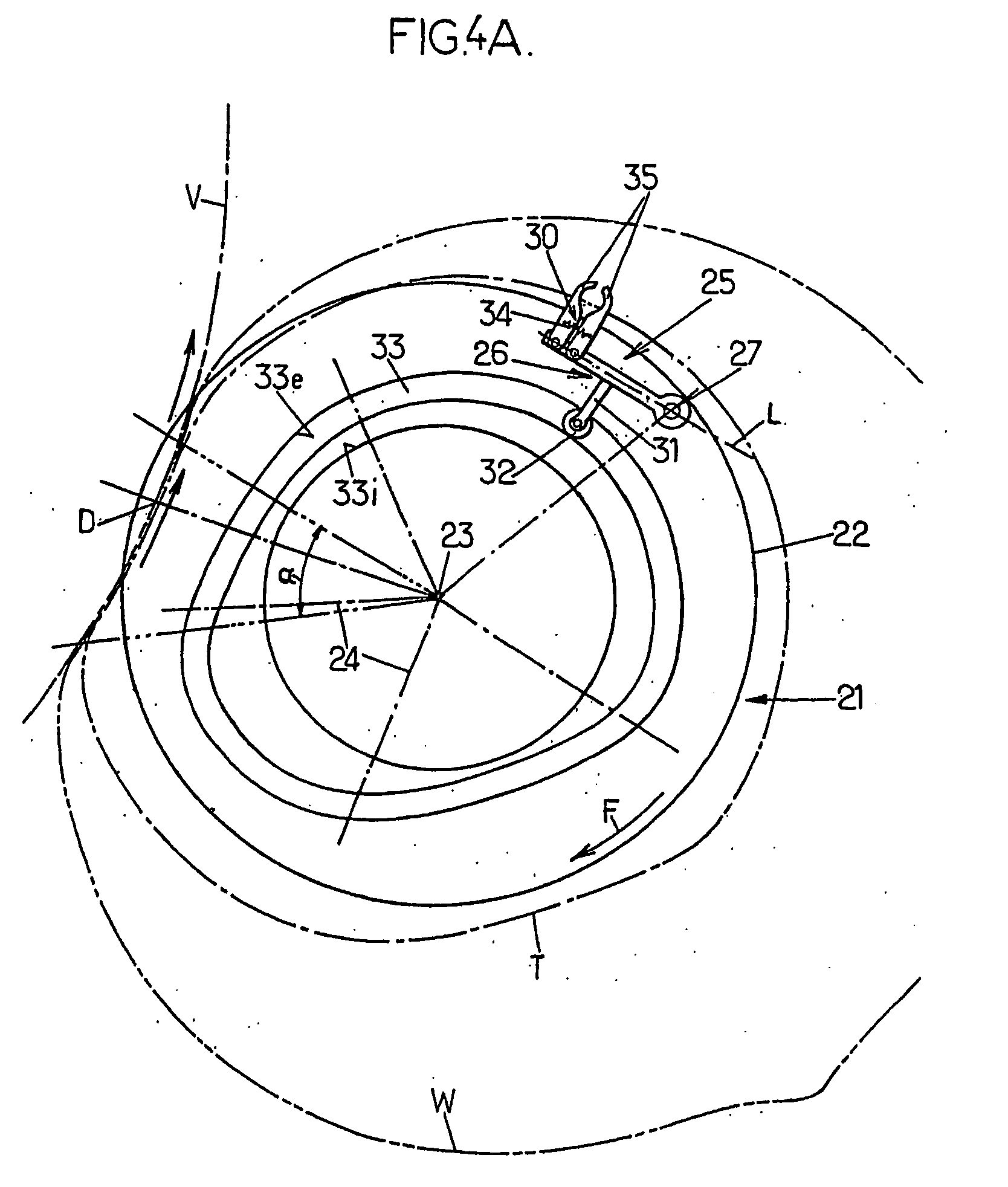
[0050]With reference to FIG. 4A initially, the conveyor device according to the invention has a rotary base 21 (corresponding to the rotary plate 1 of the prior art device) which can advantageously comprise a rotary plate 22 rotating about a vertical axis 23.

[0051]The plate 22 supports at least one mobile assembly 25 (and in practice a plurality of assemblies), which is designed as follows. A main arm 26 is supported pivotably on the plate 22 by means of a vertical shaft 27, the main arm 26 being capable of pivoting in a horizontal plane, substantially parallel to the plane of the plate 22. A gripping pincer 30 is mounted on the free end of the main arm 26, and this gripping pincer 30 extends approximately transversely to the arm 26. Finally, at least one freely rotating follower roller 32 is connected solidly to the main arm 26 and interacts with a fixed cam 33 having a curvilinear profile closed on itself about the axis 23. The roller 32 can be mounted at the end of a lever arm 31...


PUM


Abstract

Rotary device for transferring containers, with a base (21) rotating about an axis (23) and supporting a mobile assembly (25) comprising: a main arm (26) pivoting (27) on the base, a gripping pincer (30) at the free end of the main arm, and a rotary roller (32) which is solidly connected to the main arm and interacts with a fixed curvilinear cam (33) with a closed contour; the pivot shaft (27) and the free end of the main arm define a line (L) which extends approximately tangentially to the circular trajectory of the pivot axis, which precedes the free end of the arm in the direction (F) of rotation of the base; the cam is such that, when the base rotates, the end of the main arm is moved approximately radially; and the gripping pincer mounted on the free end of the main arm follows a predetermined circular path, having inverse convexity with respect to the trajectory of the rotary base, within a fixed angular range (a) of rotation of the base.

Description

FIELD OF THE INVENTION[0001]The present invention relates to improvements made to rotary devices for transferring containers, each having a rotary base which rotates continuously about an axis of rotation and which supports at least one moving assembly comprising:[0002]a main arm mounted pivotably on said base by means of a pivot shaft,[0003]a gripping pincer mounted on the free end of said main arm, and[0004]at least one freely rotating cam follower roller connected solidly to said main arm and capable of interacting with a fixed curvilinear cam extending along a closed contour.[0005]In the following text, the term “container” can be applied, depending on the positioning of the conveyor device within the installation, to a blank container, such as a preform or an intermediate container, before it is placed in a mold, or to a container (final or intermediate) after it has been shaped in a mold.BACKGROUND OF THE INVENTION[0006]The devices to which the invention relates are used in in...

Claims


Application Information

Patent Timeline
Patent Type & Authority Applications(United States)
IPC IPC(8): B65G47/84B65G29/00
CPCB65G2201/0244B65G47/847
Inventor LEGALLAIS, STEPHANE
Owner SIDEL PARTICIPATIONS SAS
Why Eureka
Eureka Blog
Learn More