
Lamp driving circuit, inverter board and display apparatus having the same

Inactive Publication Date: 2008-08-14
SAMSUNG DISPLAY CO LTD
View PDF7 Cites 5 Cited by
  • Summary
  • Abstract
  • Description
  • Claims
  • Application Information

AI Technical Summary

Benefits of technology

[0009]The present invention provides a lamp driving circuit capable of preventing a flickering phenomenon of a lamp.
[0017]According to the above, the direct current voltage from an external device is converted to the first square wave voltage having less noise, and the first square wave voltage is compared with a reference voltage to generate the second square wave voltage. Since turn-on and turn-off of the lamp are controlled based on the duty ratio of the second square wave voltage, a flickering phenomenon caused by the noise may be prevented.

Problems solved by technology

However, since the tube current control does not work when the tube current is low, the PWM control method has been mainly used for the LCD instead of the tube current control method.
However, noise occurs between the triangle wave voltage and the direct current voltage, so that the square wave voltage is distorted.

Method used


Image

  • Lamp driving circuit, inverter board and display apparatus having the same
  • Lamp driving circuit, inverter board and display apparatus having the same
  • Lamp driving circuit, inverter board and display apparatus having the same

Examples


Embodiment Construction

[0025]Hereinafter, the present invention is explained in detail with reference to the accompanying drawings. In the drawings, the thickness of layers, films, and regions are exaggerated for clarity. Like numerals refer to like elements throughout. It will be understood that when an element such as a layer, film, region, or substrate is referred to as being “on” another element, it can be directly on the other element or intervening elements may also be present.

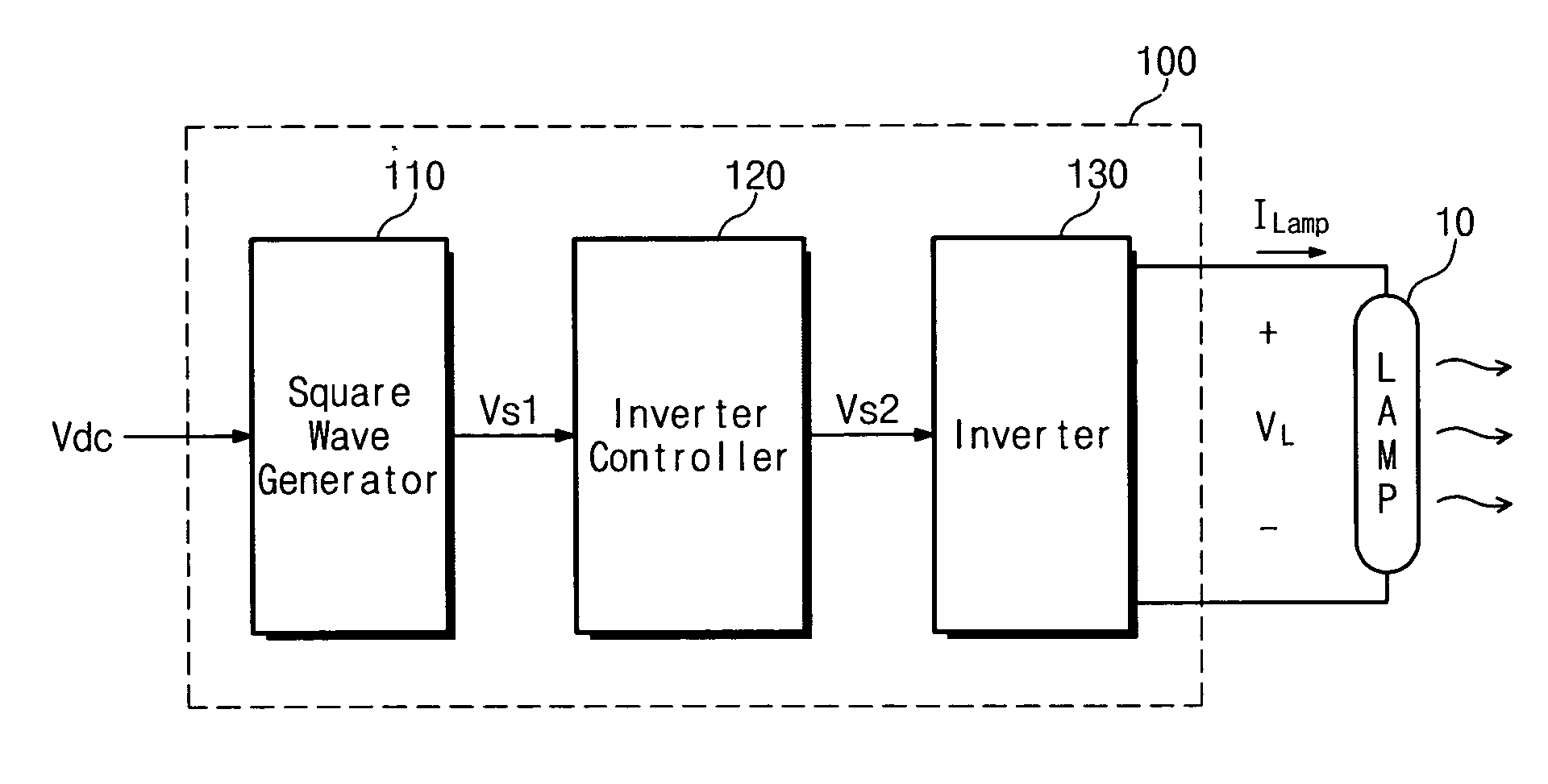
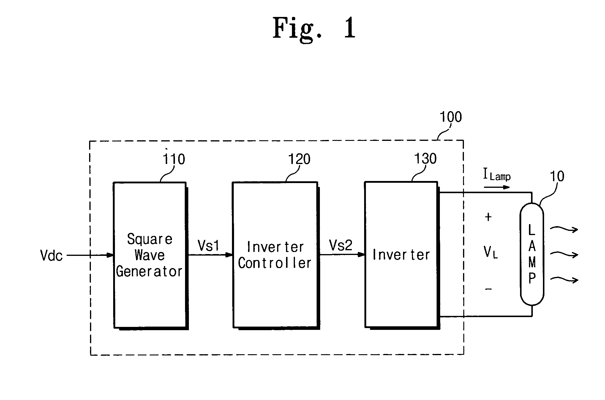
[0026]FIG. 1 is a block diagram showing an exemplary embodiment of a lamp driving circuit according to the present invention.

[0027]Referring to FIG. 1, a lamp driving circuit 100 includes a square wave generator 110, an inverter controller 120 and an inverter 130.

[0028]The square wave generator 110 receives a direct current voltage Vdc from an external device and generates a first square wave voltage Vs1 having a duty ratio which is a function of the magnitude of the direct current voltage Vdc. In the present embodiment, the d...


PUM


Abstract

A lamp driving circuit, an inverter board and a display apparatus having the inverter board, the lamp driving circuit receiving a direct current voltage and provides the direct current voltage to a square wave generator, and the square wave generator outputting a first square wave voltage having a duty ratio corresponding to a voltage level of the direct current voltage. An inverter controller compares the first square wave voltage with a reference voltage and outputs a second square wave voltage. An inverter provides an output of a lamp driving voltage according to the duty ratio of the second square wave voltage.

Description

CROSS-REFERENCE TO RELATED APPLICATION[0001]This application relies for priority upon Korean Patent Application No. 10-2007-15004 filed on Feb. 13, 2007, the contents of which are herein incorporated by reference in its entirety.BACKGROUND OF THE INVENTION[0002]1. Field of the Invention[0003]The present invention relates to a lamp driving circuit, an inverter board and a display apparatus having the inverter board. More particularly, the present invention relates to a lamp driving circuit, an inverter board and a display apparatus having the inverter board, capable of preventing a flickering phenomenon of a light from a lamp.[0004]2. Description of the Related Art[0005]In general, a liquid crystal display (LCD) includes a liquid crystal display panel displaying images and a backlight providing the liquid crystal display panel with light. Some backlights employ a cold cathode fluorescent lamp (CCFL) as a light source.[0006]Recently, LCDs have utilized a dimming method to control brig...

Claims


Application Information

Patent Timeline
IPC IPC(8): H05B37/02G09G3/36
CPCH05B41/2858Y02B20/186H05B41/3921Y02B20/00G02F1/1335H05B41/14H05B41/24H05B41/38
Inventor JEONG, YOUNG-CHEOL
Owner SAMSUNG DISPLAY CO LTD
Learn More