
Image forming apparatus

a technology of image forming and forming cartridges, which is applied in the direction of electrographic process apparatus, instruments, optics, etc., can solve the problems of reducing the efficiency with which a user can replace a developer cartridge, the conventional development delivering apparatus described above is unsatisfactory, and the stability of the amount of work is not likely to remain stable, so as to achieve stable amount, reduce the amount of work, and the frequency is low

Active Publication Date: 2008-08-07
CANON KK
View PDF9 Cites 15 Cited by
  • Summary
  • Abstract
  • Description
  • Claims
  • Application Information

AI Technical Summary

Benefits of technology

[0015]Thus, the primary object of the present invention which was made in consideration of the problems described above is to provide an image forming apparatus which is substantially lower in the frequency with which a user has to replace a developer cartridge, being therefore smaller in the amount of work which a user has to do to replace a developer cartridge, than a conventional image forming apparatus, and yet, is stable in the amount by which developer is delivered to its developing apparatus.

Problems solved by technology

Therefore, in the case of the conventional developer dispensing apparatus (disclosed in Japanese Laid-open Patent Application 2005-54072), the developer from the developer cartridge is temporarily stored in the developer storage of the developer dispensing apparatus, since the amount by which developer is delivered from the developer cartridge is affected by the amount of the developer remaining in the developer cartridge, being therefore unlikely to remain stable.
However, with the recent increase in the operational speed of an image forming apparatus, and / or the usage of an image forming apparatus in the field of the POD (print-on-demand) business (which puts image forming apparatus to substantially heavier usage than an ordinary user), the conventional developing delivering apparatuses described above have become unsatisfactory.
However, simply increasing a developer cartridge in size (capacity) reduces the efficiency with which a user can replace a developer cartridge.
Further, if a developer cartridge packed with a large amount of developer is left in storage for a substantial length of time, the developer in the cartridge is likely to solidify.
The solidified developer is likely to add to the abovementioned problem.
In other words, simply increasing a developer cartridge in size is likely to add to the abovementioned problems when the cartridge is put to actual use.
Further, it contributes very little to the solving of the problem that the amount by which developer can be discharged from a developer cartridge is affected by the changes in the amount of the developer remaining in the developer cartridge.
However, increasing a developer cartridge in capacity (size) makes it necessary to increase a developer dispensing apparatus in size, making it difficult to place a developer dispensing apparatus (which is large in capacity) in the adjacencies of a developing apparatus.
Thus, a developer dispensing apparatus capable of accommodating a developer cartridge of a large capacity is lower in the accuracy with which it delivers developer to the developing apparatus, being therefore likely to make the toner density of the developer in the developing apparatus fluctuate.

Method used


Image

  • Image forming apparatus
  • Image forming apparatus
  • Image forming apparatus

Examples


embodiment 1

(1) Example of Image Forming Apparatus

[0032]FIG. 3 is a schematic sectional view of the image forming apparatus in this embodiment of the present invention, and shows the general structure of the apparatus. This image forming apparatus is an electrophotographic full-color laser printer which employs an intermediary transfer belt and four photosensitive members. The four photosensitive drums are juxtaposed in parallel (arranged in tandem). The image forming apparatus outputs on a sheet of recording medium P, an image which reflects electrical pictorial signals inputted from an external host apparatus 200 connected to the control circuit 100 (CPU). The external host apparatus 200 is a computer, an image reader, or the like.

[0033]The printer 1 has four image forming portions Y, M, C, and K (first to fourth image forming portions, counting from left to right in drawing), which are in the internal space of the main assembly of the printer, being juxtaposed in parallel. The four image for...

embodiment 2

[0085]Next, referring to FIGS. 8, 9A, and 9B, the second embodiment of the present invention will be described.

[0086]FIG. 8 is a schematic sectional view of the first portion 52 of the developer dispensing apparatus in the second embodiment of the present invention. Incidentally, the structural components in this embodiment, which are the same in function as those in the above described first embodiment, are given the same referential symbols as those given to the corresponding components in the first embodiment, and will not be described here.

[0087]The main assembly of the printer (image forming apparatus) in this embodiment is different from that in the first embodiment in that the first portion 52 of its developer dispensing apparatus is different in structure from the corresponding portion in the first embodiment. That is, the first developer storage 52a of the first portion 52 of the developer dispensing apparatus, shown in FIG. 8, is roughly twice in developer capacity as the ...

embodiment 3

[0093]Next, the third embodiment of the present invention will be described.

[0094]In terms of printer structure, this embodiment is the same as the second embodiment. The developer delivering operation in this embodiment, however, is carried out as shown by FIG. 10 which is a flowchart of the developer dispensing sequence in this embodiment.

[0095]In the case of the printer in this embodiment, which is the same in structure as that in the second embodiment, if it is determined that the empty space in the first developer storage 52a has become larger than the developer capacity of the developer cartridge 51, the control circuit 100 makes the speed at which developer is discharged by the developer discharging means 54, 56, and 59, faster than the normal speed.

[0096]Normally, as the developer in the first developer storage 52a of the first portion 52 of the developer dispensing apparatus is consumed by a printing operation, it eventually becomes impossible for the developer in the first...


PUM


Abstract

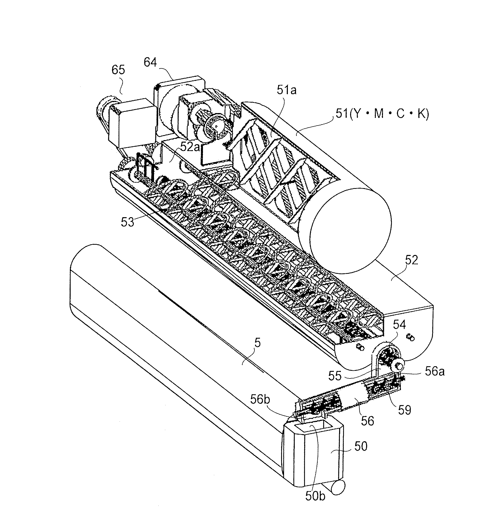
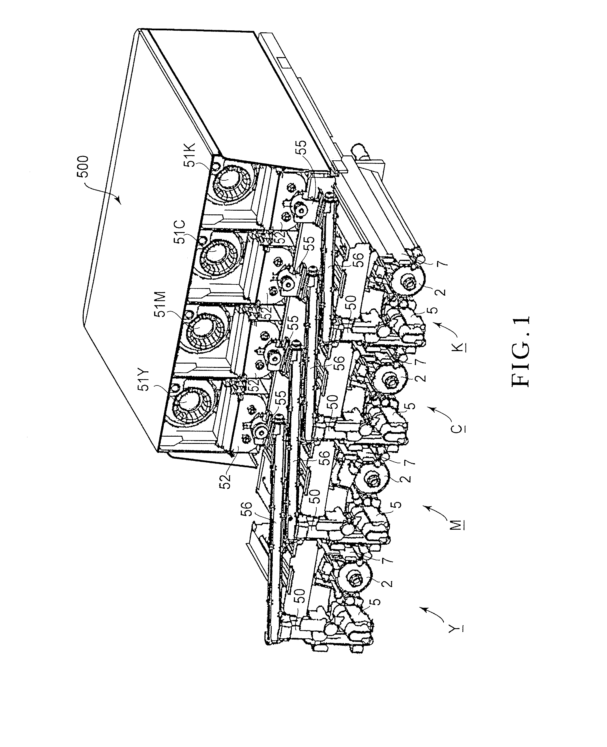
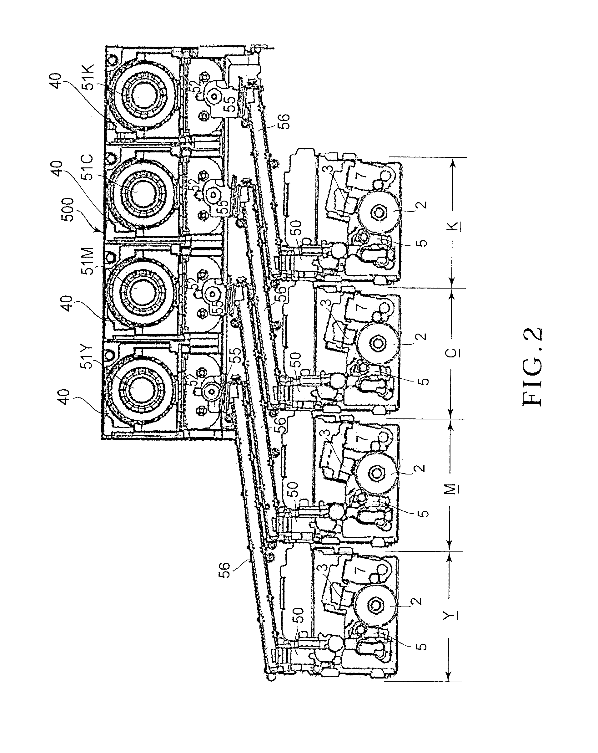
An image forming apparatus includes an image bearing member on which an electrostatic image is to be formed; a developing device for developing the electrostatic image with a developer; a developer container detachably mountable to a mounting portion provided in a main assembly of the apparatus, for accommodating a supply of developer; a discharging device for discharging the supply of developer from the developer container mounted to the mounting portion to an outside of the developer container; a first developer accommodating portion for receiving the developer from the discharging device and for accommodating an amount of the developer which exceeds a first predetermined amount, wherein the first amount is larger than a capacity of the developer container; a first detecting device for detecting an amount of the developer in the first accommodating portion; a first supplying device for supplying the developer in the first accommodating portion to an outside of the first accommodating portion; a second developer accommodating portion for receiving the developer from the first supplying device and for accommodating an amount of the developer which exceeds a second predetermined amount; a second detecting device for detecting the amount in the second accommodating portion; a second supplying device for supplying the developer from the second accommodating portion toward the developing device; a controller for controlling, when the developer is accommodated in the developing container, the discharging device such that amount of the developer in the first accommodating portion is not less than the first amount, in accordance with a detection result of the first detecting device and such that such that amount of the developer in the second accommodating portion is not less than the second amount, in accordance with a detection result of the second detecting device, and for permitting, when the developing container is substantially empty, and the amount in the first accommodating portion is less than the first value, an image forming operation to continue until the amount in the second developer portion becomes less than the second amount.

Description

FIELD OF THE INVENTION AND RELATED ART[0001]The present invention relates to an image forming apparatus such as an electrophotographic copying machine, printer, etc.[0002]In the field of an image forming apparatus, such as an electrophotographic copying machine, printer, etc., a replaceable developer cartridge is employed to make it easier for a user to replenish a developing apparatus with developer (toner) without contaminating the user s hand with developer (toner).[0003]Generally, in the case of an image forming apparatus which is excellent in operability, its developer cartridge slots are located on top, or in the top portion, of the main assembly of the image forming apparatus. A developer cartridge is to be set in the developer cartridge slot by a user. As a developer cartridge is mounted in the developer cartridge slot, the developer in the developer cartridge is delivered, as necessary, from the developer cartridge to the developing apparatus of the image forming apparatus,...

Claims


Application Information

Patent Timeline
Patent Type & Authority Applications(United States)
IPC IPC(8): G03G15/08
CPCG03G15/0896G03G2215/0819G03G15/0877G03G15/0872G03G15/0879G03G2215/0888G03G15/06
Inventor MIURA, YUKIHIROSUZUKI, TAKAYUKIYAHAGI, TAKASHI
Owner CANON KK
Learn More